DE69733486T2 - BLOOD GENERATION DEVICE FOR DIAGNOSTIC TESTS - Google Patents

BLOOD GENERATION DEVICE FOR DIAGNOSTIC TESTS Download PDF

Info

Publication number
DE69733486T2
DE69733486T2 DE69733486T DE69733486T DE69733486T2 DE 69733486 T2 DE69733486 T2 DE 69733486T2 DE 69733486 T DE69733486 T DE 69733486T DE 69733486 T DE69733486 T DE 69733486T DE 69733486 T2 DE69733486 T2 DE 69733486T2
Authority
DE
Germany
Prior art keywords
blood
skin
lancet
opening
vacuum
Prior art date
Legal status (The legal status is an assumption and is not a legal conclusion. Google has not performed a legal analysis and makes no representation as to the accuracy of the status listed.)
Expired - Lifetime
Application number
DE69733486T
Other languages
German (de)
Other versions
DE69733486D1 (en
Inventor
D. David CUNNINGHAM
P. Timothy HENNING
B. Eric SHAIN
F. Douglas YOUNG
G. Michael LOWERY
G. Thomas SCHAPIRA
W. Hugh GRAHAM
J. Andrew MUETTERTIES
R. Geoffrey CHAMBERS
J. Graham Headington HUGHES
L. Jared Abingdon WATKIN
F. Gary PROKOP
P. Joshua GOLDFARB
Current Assignee (The listed assignees may be inaccurate. Google has not performed a legal analysis and makes no representation or warranty as to the accuracy of the list.)
Abbott Laboratories
Original Assignee
Abbott Laboratories
Priority date (The priority date is an assumption and is not a legal conclusion. Google has not performed a legal analysis and makes no representation as to the accuracy of the date listed.)
Filing date
Publication date
Priority claimed from US08/759,698 external-priority patent/US6063039A/en
Application filed by Abbott Laboratories filed Critical Abbott Laboratories
Publication of DE69733486D1 publication Critical patent/DE69733486D1/en
Application granted granted Critical
Publication of DE69733486T2 publication Critical patent/DE69733486T2/en
Anticipated expiration legal-status Critical
Expired - Lifetime legal-status Critical Current

Links

Classifications

    • AHUMAN NECESSITIES
    • A61MEDICAL OR VETERINARY SCIENCE; HYGIENE
    • A61BDIAGNOSIS; SURGERY; IDENTIFICATION
    • A61B5/00Measuring for diagnostic purposes; Identification of persons
    • A61B5/15Devices for taking samples of blood
    • A61B5/151Devices specially adapted for taking samples of capillary blood, e.g. by lancets, needles or blades
    • A61B5/15186Devices loaded with a single lancet, i.e. a single lancet with or without a casing is loaded into a reusable drive device and then discarded after use; drive devices reloadable for multiple use
    • AHUMAN NECESSITIES
    • A61MEDICAL OR VETERINARY SCIENCE; HYGIENE
    • A61BDIAGNOSIS; SURGERY; IDENTIFICATION
    • A61B5/00Measuring for diagnostic purposes; Identification of persons
    • A61B5/145Measuring characteristics of blood in vivo, e.g. gas concentration, pH value; Measuring characteristics of body fluids or tissues, e.g. interstitial fluid, cerebral tissue
    • A61B5/14532Measuring characteristics of blood in vivo, e.g. gas concentration, pH value; Measuring characteristics of body fluids or tissues, e.g. interstitial fluid, cerebral tissue for measuring glucose, e.g. by tissue impedance measurement
    • AHUMAN NECESSITIES
    • A61MEDICAL OR VETERINARY SCIENCE; HYGIENE
    • A61BDIAGNOSIS; SURGERY; IDENTIFICATION
    • A61B5/00Measuring for diagnostic purposes; Identification of persons
    • A61B5/145Measuring characteristics of blood in vivo, e.g. gas concentration, pH value; Measuring characteristics of body fluids or tissues, e.g. interstitial fluid, cerebral tissue
    • A61B5/1486Measuring characteristics of blood in vivo, e.g. gas concentration, pH value; Measuring characteristics of body fluids or tissues, e.g. interstitial fluid, cerebral tissue using enzyme electrodes, e.g. with immobilised oxidase
    • AHUMAN NECESSITIES
    • A61MEDICAL OR VETERINARY SCIENCE; HYGIENE
    • A61BDIAGNOSIS; SURGERY; IDENTIFICATION
    • A61B5/00Measuring for diagnostic purposes; Identification of persons
    • A61B5/15Devices for taking samples of blood
    • A61B5/150007Details
    • A61B5/150015Source of blood
    • A61B5/150022Source of blood for capillary blood or interstitial fluid
    • AHUMAN NECESSITIES
    • A61MEDICAL OR VETERINARY SCIENCE; HYGIENE
    • A61BDIAGNOSIS; SURGERY; IDENTIFICATION
    • A61B5/00Measuring for diagnostic purposes; Identification of persons
    • A61B5/15Devices for taking samples of blood
    • A61B5/150007Details
    • A61B5/150053Details for enhanced collection of blood or interstitial fluid at the sample site, e.g. by applying compression, heat, vibration, ultrasound, suction or vacuum to tissue; for reduction of pain or discomfort; Skin piercing elements, e.g. blades, needles, lancets or canulas, with adjustable piercing speed
    • A61B5/150061Means for enhancing collection
    • A61B5/150068Means for enhancing collection by tissue compression, e.g. with specially designed surface of device contacting the skin area to be pierced
    • AHUMAN NECESSITIES
    • A61MEDICAL OR VETERINARY SCIENCE; HYGIENE
    • A61BDIAGNOSIS; SURGERY; IDENTIFICATION
    • A61B5/00Measuring for diagnostic purposes; Identification of persons
    • A61B5/15Devices for taking samples of blood
    • A61B5/150007Details
    • A61B5/150053Details for enhanced collection of blood or interstitial fluid at the sample site, e.g. by applying compression, heat, vibration, ultrasound, suction or vacuum to tissue; for reduction of pain or discomfort; Skin piercing elements, e.g. blades, needles, lancets or canulas, with adjustable piercing speed
    • A61B5/150061Means for enhancing collection
    • A61B5/150076Means for enhancing collection by heating
    • AHUMAN NECESSITIES
    • A61MEDICAL OR VETERINARY SCIENCE; HYGIENE
    • A61BDIAGNOSIS; SURGERY; IDENTIFICATION
    • A61B5/00Measuring for diagnostic purposes; Identification of persons
    • A61B5/15Devices for taking samples of blood
    • A61B5/150007Details
    • A61B5/150053Details for enhanced collection of blood or interstitial fluid at the sample site, e.g. by applying compression, heat, vibration, ultrasound, suction or vacuum to tissue; for reduction of pain or discomfort; Skin piercing elements, e.g. blades, needles, lancets or canulas, with adjustable piercing speed
    • A61B5/150061Means for enhancing collection
    • A61B5/150099Means for enhancing collection by negative pressure, other than vacuum extraction into a syringe by pulling on the piston rod or into pre-evacuated tubes
    • AHUMAN NECESSITIES
    • A61MEDICAL OR VETERINARY SCIENCE; HYGIENE
    • A61BDIAGNOSIS; SURGERY; IDENTIFICATION
    • A61B5/00Measuring for diagnostic purposes; Identification of persons
    • A61B5/15Devices for taking samples of blood
    • A61B5/150007Details
    • A61B5/150206Construction or design features not otherwise provided for; manufacturing or production; packages; sterilisation of piercing element, piercing device or sampling device
    • A61B5/150221Valves
    • AHUMAN NECESSITIES
    • A61MEDICAL OR VETERINARY SCIENCE; HYGIENE
    • A61BDIAGNOSIS; SURGERY; IDENTIFICATION
    • A61B5/00Measuring for diagnostic purposes; Identification of persons
    • A61B5/15Devices for taking samples of blood
    • A61B5/150007Details
    • A61B5/150374Details of piercing elements or protective means for preventing accidental injuries by such piercing elements
    • A61B5/150381Design of piercing elements
    • A61B5/150412Pointed piercing elements, e.g. needles, lancets for piercing the skin
    • AHUMAN NECESSITIES
    • A61MEDICAL OR VETERINARY SCIENCE; HYGIENE
    • A61BDIAGNOSIS; SURGERY; IDENTIFICATION
    • A61B5/00Measuring for diagnostic purposes; Identification of persons
    • A61B5/15Devices for taking samples of blood
    • A61B5/150007Details
    • A61B5/150374Details of piercing elements or protective means for preventing accidental injuries by such piercing elements
    • A61B5/150381Design of piercing elements
    • A61B5/150503Single-ended needles
    • AHUMAN NECESSITIES
    • A61MEDICAL OR VETERINARY SCIENCE; HYGIENE
    • A61BDIAGNOSIS; SURGERY; IDENTIFICATION
    • A61B5/00Measuring for diagnostic purposes; Identification of persons
    • A61B5/15Devices for taking samples of blood
    • A61B5/150007Details
    • A61B5/150374Details of piercing elements or protective means for preventing accidental injuries by such piercing elements
    • A61B5/150534Design of protective means for piercing elements for preventing accidental needle sticks, e.g. shields, caps, protectors, axially extensible sleeves, pivotable protective sleeves
    • A61B5/150664Pivotable protective sleeves, i.e. sleeves connected to, or integrated in, the piercing or driving device, and which are pivoted for covering or uncovering the piercing element
    • AHUMAN NECESSITIES
    • A61MEDICAL OR VETERINARY SCIENCE; HYGIENE
    • A61BDIAGNOSIS; SURGERY; IDENTIFICATION
    • A61B5/00Measuring for diagnostic purposes; Identification of persons
    • A61B5/15Devices for taking samples of blood
    • A61B5/151Devices specially adapted for taking samples of capillary blood, e.g. by lancets, needles or blades
    • A61B5/15101Details
    • A61B5/15103Piercing procedure
    • A61B5/15107Piercing being assisted by a triggering mechanism
    • A61B5/15113Manually triggered, i.e. the triggering requires a deliberate action by the user such as pressing a drive button
    • AHUMAN NECESSITIES
    • A61MEDICAL OR VETERINARY SCIENCE; HYGIENE
    • A61BDIAGNOSIS; SURGERY; IDENTIFICATION
    • A61B5/00Measuring for diagnostic purposes; Identification of persons
    • A61B5/15Devices for taking samples of blood
    • A61B5/151Devices specially adapted for taking samples of capillary blood, e.g. by lancets, needles or blades
    • A61B5/15101Details
    • A61B5/15115Driving means for propelling the piercing element to pierce the skin, e.g. comprising mechanisms based on shape memory alloys, magnetism, solenoids, piezoelectric effect, biased elements, resilient elements, vacuum or compressed fluids
    • A61B5/15125Driving means for propelling the piercing element to pierce the skin, e.g. comprising mechanisms based on shape memory alloys, magnetism, solenoids, piezoelectric effect, biased elements, resilient elements, vacuum or compressed fluids comprising a vacuum or compressed fluids
    • AHUMAN NECESSITIES
    • A61MEDICAL OR VETERINARY SCIENCE; HYGIENE
    • A61BDIAGNOSIS; SURGERY; IDENTIFICATION
    • A61B5/00Measuring for diagnostic purposes; Identification of persons
    • A61B5/15Devices for taking samples of blood
    • A61B5/151Devices specially adapted for taking samples of capillary blood, e.g. by lancets, needles or blades
    • A61B5/15186Devices loaded with a single lancet, i.e. a single lancet with or without a casing is loaded into a reusable drive device and then discarded after use; drive devices reloadable for multiple use
    • A61B5/15188Constructional features of reusable driving devices
    • A61B5/1519Constructional features of reusable driving devices comprising driving means, e.g. a spring, for propelling the piercing unit
    • AHUMAN NECESSITIES
    • A61MEDICAL OR VETERINARY SCIENCE; HYGIENE
    • A61BDIAGNOSIS; SURGERY; IDENTIFICATION
    • A61B5/00Measuring for diagnostic purposes; Identification of persons
    • A61B5/15Devices for taking samples of blood
    • A61B5/151Devices specially adapted for taking samples of capillary blood, e.g. by lancets, needles or blades
    • A61B5/15186Devices loaded with a single lancet, i.e. a single lancet with or without a casing is loaded into a reusable drive device and then discarded after use; drive devices reloadable for multiple use
    • A61B5/15188Constructional features of reusable driving devices
    • A61B5/15192Constructional features of reusable driving devices comprising driving means, e.g. a spring, for retracting the lancet unit into the driving device housing
    • A61B5/15194Constructional features of reusable driving devices comprising driving means, e.g. a spring, for retracting the lancet unit into the driving device housing fully automatically retracted, i.e. the retraction does not require a deliberate action by the user, e.g. by terminating the contact with the patient's skin
    • AHUMAN NECESSITIES
    • A61MEDICAL OR VETERINARY SCIENCE; HYGIENE
    • A61BDIAGNOSIS; SURGERY; IDENTIFICATION
    • A61B5/00Measuring for diagnostic purposes; Identification of persons
    • A61B5/15Devices for taking samples of blood
    • A61B5/157Devices characterised by integrated means for measuring characteristics of blood
    • AHUMAN NECESSITIES
    • A61MEDICAL OR VETERINARY SCIENCE; HYGIENE
    • A61BDIAGNOSIS; SURGERY; IDENTIFICATION
    • A61B5/00Measuring for diagnostic purposes; Identification of persons
    • A61B5/41Detecting, measuring or recording for evaluating the immune or lymphatic systems
    • A61B5/411Detecting or monitoring allergy or intolerance reactions to an allergenic agent or substance
    • AHUMAN NECESSITIES
    • A61MEDICAL OR VETERINARY SCIENCE; HYGIENE
    • A61BDIAGNOSIS; SURGERY; IDENTIFICATION
    • A61B2562/00Details of sensors; Constructional details of sensor housings or probes; Accessories for sensors
    • A61B2562/02Details of sensors specially adapted for in-vivo measurements
    • A61B2562/0295Strip shaped analyte sensors for apparatus classified in A61B5/145 or A61B5/157
    • AHUMAN NECESSITIES
    • A61MEDICAL OR VETERINARY SCIENCE; HYGIENE
    • A61BDIAGNOSIS; SURGERY; IDENTIFICATION
    • A61B5/00Measuring for diagnostic purposes; Identification of persons
    • A61B5/15Devices for taking samples of blood
    • A61B5/150007Details
    • A61B5/150358Strips for collecting blood, e.g. absorbent

Abstract

Method and apparatus for obtaining a sample of blood from a patient for subsequent diagnostic tests, e.g., glucose monitoring. In one aspect of the invention, the method comprises the steps of: (a) forming an unobstructed opening in the area of the skin from which the sample of blood is to be extracted; and (b) extracting the sample of blood from the unobstructed opening in the skin, with the aid of a vacuum and a stretching of the skin. In another aspect of the invention, an apparatus for carrying out the method described previously is provided. The apparatus comprises: (a) a device for forming an unobstructed opening in an area of skin from which said sample is to be extracted, preferably a lancing assembly; and (b) a vacuum pump. Preferably, the apparatus also includes a housing. In a further aspect of the invention, a pneumatic lancing assembly is provided. The pneumatic lancing assembly uses differential gas pressure to thrust a lancer into skin tissue. In another aspect of this invention, an article is provided for an article capable of both collecting blood and detecting an analyte in that blood. The article, which contains an appropriate detection element for determining the amount of analyte in the blood, can be used in conjunction with a meter that measures the signal generated by the detection element of the article.

Description

HINTERGRUND DER ERFINDUNGBACKGROUND OF THE INVENTION

1. Erfindungsgebiet1. Field of the invention

Diese Erfindung betrifft ein Gerät, um Proben von Blut für Diagnosezwecke zu erhalten.These Invention relates to a device to get samples of blood for To obtain diagnostic purposes.

2. Erörterung des Standes der Technik2. Discussion of the Prior Art

Die Vorherrschaft von Diabetes ist in der Welt bemerkenswert angestiegen. Zu diesem Zeitpunkt stellen etwa 3% der Bevölkerung der Vereinigten Staaten diagnostizierte Diabetiker dar. Es wird angenommen, dass die eigentliche Gesamtzahl von Diabetikern in den Vereinigten Staaten über 16.000.000 ist. Diabetes kann zu zahlreichen Komplikationen wie z. B. Retinopathie, Nephropathie und Neuropathie führen.The Supremacy of diabetes has increased remarkably in the world. At this time, about 3% of the population represent the United States diagnosed diabetics. It is believed that the actual Total number of diabetics in the United States over 16,000,000 is. Diabetes can lead to numerous complications such as Retinopathy, Nephropathy and neuropathy.

Der wichtigste Faktor zum Reduzieren der mit Diabetes verknüpften Komplikationen ist die Beibehaltung eines richtigen Glukosespiegels im Blutstrom. Die Beibehaltung des richtigen Glukosespiegels im Blutstrom kann viele der Wirkungen von Diabetes sogar umkehren.Of the most important factor in reducing diabetes-related complications is the maintenance of a proper glucose level in the bloodstream. Maintaining the right glucose level in the bloodstream can even reverse many of the effects of diabetes.

Glukoseüberwachungsvorrichtungen aus dem Stand der Technik haben am Prinzip der Blutentnahme an Individuen mittels einer Vielfalt an Verfahren wie beispielsweise einer Nadel oder Lanzette gearbeitet. Eine Person überzieht dann einen Papierstreifen, auf dem eine Chemikalie aufgetragen ist, mit dem Blut und steckt schließlich die mit Blut überzogenen Streifen in einen Blutglukosemesser, um die Glukosekonzentration durch die Bestimmung der Änderung des Reflexionsvermögens zu messen.Glucose monitoring devices From the prior art have the principle of blood collection of individuals by a variety of methods such as a needle or lancet worked. A person then covers a piece of paper on which a chemical is applied, with the blood and finally puts the covered with blood Strip into a blood glucose meter to increase the glucose concentration by determining the change of reflectivity to eat.

Das medizinische Gerät aus dem Stand der Technik zum Überwachen des Glukosespiegels im Blutstrom erforderte, dass eine Person eigens eine Nadel oder Lanzette zur Blutentnahme des Individuums, Streifen, die die Blutchemikalie mit sich führen, die eine chemische Reaktion auf die Glukose im Blutstrom erzeugen und die Farbe wechseln, und einen Blutglukosemesser zum Ablesen der Farbänderung, die den Glukosespiegel im Blutstrom anzeigt. Der Blutglukosespiegel, wird, wenn von einem Glukosemesser gemessen, mittels des gut bekannten Verfahrens zum Lesen des Reflexionsvermögens für die Glukoseoxidation von einem die Blutchemikalie mitführenden Streifen gelesen.The medical device from the prior art for monitoring The level of glucose in the bloodstream required one person to do it a needle or lancet for taking the blood of the individual, strips, that carry the blood chemical, which is a chemical reaction to produce the glucose in the bloodstream and change color, and a blood glucose meter for reading the color change, which is the glucose level in the bloodstream. The blood glucose level will, if of one Glucose meter measured by the well-known method for Reading the reflectivity for the Glucose oxidation from a blood chemical carrying Strip read.

Im allgemeinen umfassen Lanzetten eine Klinge und ein daran entgegengesetztes anpressbares Ende, wobei die Klinge ein spitzes Ende hat und in der Lage ist, in die Haut einer Person gestoßen zu werden. Durch das Klopfen des anpressbaren Abschnitts wird das spitze Ende der Klinge beispielsweise die Haut des Fingers einstechen. Die Finger-Lanzette wird vorrangig verwendet, um kleine Blutmengen, d. h. weniger als 1 ml, zu erhalten. Diabetiker verwenden die Finger-Lanzette, um für die Analyse von Glukose Blutmengen von weniger als 25 μl zu erhalten. Eine geringe Blutmenge für den Bluttest wird aus der Haut heraussickern. Es gibt viele kleine Blutgefäße in jedem Finger, so dass ein Finger gequetscht werden kann, damit ein größerer Bluttropfen heraus sickert. Der Finger ist einer der empfindlichsten Teile des Körpers; entsprechend ruft die Lanzette sogar größere Schmerzen hervor, als man sie erwarten würde, wenn mithilfe der Lanzette Blut an einer anderen Körperstelle extrahiert würde. Die Finger-Lanzette stellt aufgrund des eingeschränkten Bereichs, der für das Einschneiden an den Fingern zur Verfügung steht, ein weiteres Problem dar. Da Diabetikern empfohlen wird, ihren Blutglukosespiegel vier- bis sechsmal am Tag zu überwachen, erfordert der begrenzte Bereich an den Fingern das wiederholte Einschneiden von Bereichen, die bereits entzündet sind. Da Finger schmerzempfindlich sind, ist die jüngste Tendenz die, den Arm einer Blutprobe zu unterziehen (s. z. B. US-Patent Nr. 4.653.513). Die Vorrichtung des US-Patents Nr. 4.653.513 umfasst ein zylindrisches Gehäuse und einen Lanzettenhalter, der eine Dichtung oder einen flexiblen Abschnitt hat, der verschiebbar im Gehäuse untergebracht wird. Federn werden den Lanzettenhalter einziehen, um dadurch den Luftdruck im Gehäuse zu senken, so dass sie automatisch und sofort eine Blutprobe ansaugt, nachdem eine Lanzette die Haut einsticht. Siehe auch US-Patent Nr. 5.320.607, die eine Vorrichtung offenbart, die eine abgedichtete Vakuumkammer in einem Zustand eines vorherrschenden gesenkten Drucks, ein Stützglied für die abgedichtete Vakuumkammer, wobei das Halteglied angrenzend an der abgedichteten Vakuumkammer einen Ansaugabschnitt bestimmt, der Ansaugabschnitt in Zusammenwirkung mit der abgedichteten Vakuumkammer einen Hautbereich eines Patienten einer kleineren Druckbedingung aussetzt, wenn die Vorrichtung betätigt ist, und ein Mittel umfasst, das innerhalb des Ansaugabschnitts angeordnet ist, um eine Abschnitt des Hautbereichs eines Patienten, der der niedrigen Druckbedingung ausgesetzt wird, leicht zu zerreißen.in the Generally, lancets include a blade and an opposite one pressable end, the blade has a pointed end and in is able to be pushed into the skin of a person. By the knock of the pressable portion becomes the pointed end of the blade, for example pierce the skin of the finger. The finger lancet becomes paramount used to small amounts of blood, d. H. less than 1 ml. Diabetics use the finger lancet to order blood for the analysis of glucose less than 25 μl to obtain. A small amount of blood for the blood test will be taken from the Skin oozing out. There are many small blood vessels in each finger, so that a finger can be squeezed for a larger blood drop to seep out. The finger is one of the most sensitive parts of the body; corresponding the lancet gets even more pain forth, as you would expect, when using the lancet blood at another body site would be extracted. The finger lancet, due to the restricted area, the for the cutting on the fingers is another problem Since diabetics are recommended to increase their blood glucose to monitor six times a day, the limited area on the fingers requires repeated incision of areas that are already inflamed are. Since fingers are sensitive to pain, the most recent trend is to subject the arm to a blood sample (see, for example, U.S. Patent No. 4,653,513). The apparatus of U.S. Patent No. 4,653,513 comprises a cylindrical one casing and a lancet holder that has a gasket or a flexible one Section has, which is slidably housed in the housing. feathers will retract the lancet holder, thereby reducing the air pressure in the casing so that she automatically and immediately takes a blood sample, after a lancet punctures the skin. See also US patent no. No. 5,320,607, which discloses a device having a sealed one Vacuum chamber in a state of a prevailing lowered pressure, a support member for the sealed vacuum chamber, wherein the holding member adjacent to the sealed vacuum chamber determines a suction section, the suction section in cooperation with the sealed vacuum chamber, a skin area subject a patient to a smaller pressure condition, if the Device operated is, and comprises means within the suction section arranged to cover a portion of the skin area of a patient, which is subjected to the low pressure condition, easy to tear.

Da die Blutmengen-Erfordernisse für einen Standard-Glukose-Teststreifen für gewöhnlich 3 μl sind, muss ein Körperbereich, der soviel Blut aus einer Lanzettenwunde erzeugen kann, verwendet werden. Es wird jedoch angenommen, dass Verbesserungen in der Glukose-Teststreifentechnologie die benötigte Blutmenge von 1 bis 3 μl reduzieren wird. Da der Finger gut mit Blut versorgt wird und die Blutmenge erhöht werden kann, indem der Finger nach dem Einschneiden gequetscht wird, ist der Finger die gegenwärtig bevorzugte Körperstelle für das Einschneiden, obwohl das Einschneiden des Fingers schmerzhaft ist.Since the blood volume requirements for a standard glucose test strip are usually 3 μl, For example, a body area that can produce so much blood from a lancet wound must be used. However, it is believed that improvements in glucose test strip technology will reduce the required amount of blood from 1 to 3 μl. Since the finger is well supplied with blood and the amount of blood can be increased by squeezing the finger after incision, the finger is the presently preferred site for incision, although the incision of the finger is painful.

Eine weniger schmerzhafte Technik zum Erhalten von Körperfluiden könnte gefunden werden, wenn ein zuverlässiges Verfahren für das Einschneiden eines Körperteils, das weniger schmerzempfindlich als der Finger ist, und für das Erhalten einer nützlichen Blutmenge von diesem Körperteil gefunden würde. Ein Körperteil wie beispielsweise der Unterarm ist viel weniger schmerzempfindlich als der Finger, aber die asu dem Einschneidevorgang resultierende Blutmenge stellt für die Verwendung mit der aktuellen Erfassungstechnologie allgemein eine unangemessene Menge dar. Wege für das Erhöhen des Blutflusses an den Finger sind allgemein bekannt. Den Diabetikern wird empfohlen, ihren Finger vor dem Einschneiden unter heißes Wasser zu halten, um die Blutfluss in den Finger zu verbessern und die vom Finger entnommene Blutmenge zu erhöhen. Für Bereiche wie beispielsweise den Unterarm oder Oberschenkel ist es unpraktisch, Wasser über ein Körperteil laufen zu lassen, um den Blutfluss zu verbessern. Die Verfügbarkeit von heißem Wasser stellt auch ein Problem dar.A less painful technique for getting body fluids could be found if a reliable Procedure for the cutting of a body part, which is less sensitive to pain than the finger, and for getting a useful one Amount of blood from this body part would be found. A body part such as the forearm is much less sensitive to pain as the finger, but asu resulting from the incision Amount of blood provides for the use with current detection technology in general an inappropriate amount. Ways to increase blood flow to the Fingers are well known. Diabetics are advised to take their Keep fingers in hot water before cutting To improve blood flow to the finger and the finger removed Increase blood volume. For areas such as the forearm or thigh, it is impractical Water over one body part run to improve blood flow. The availability of hot Water is also a problem.

Das von einem Lanzettenstich erhaltene Blut wurde für gewöhnlich manuell vom Benutzer vom Finger zum Detektor überführt. Jedoch ist eine solche manuelle Überführung für Benutzer schwierig, die wenig Geschick, eine schlechte Sicht zeigen, oder die schüttel-anfällig sind (hypoglykämische Diabetiker). Die manuelle Überführung kann auch zum Fehlern bei der Glukosebestimmung führen, wenn zu viel oder zu wenig Blut überführt wird.The blood obtained from a lancet puncture was usually manually used by the user transferred from the finger to the detector. however is one such manual override for users difficult to show the low skill, a bad view, or who are shake-prone (hypoglycemic Diabetic). The manual transfer can also lead to errors in glucose determination if too much or too little blood is transferred.

Es wäre daher wünschenswert, eine Technik und ein Gerät zu entwickeln, um für Diagnosezwecke auf schmerzfreie, zuverlässige Weise Blut zu erhalten.It would be therefore desirable, a technique and a device to develop for Diagnostic purposes in a painless, reliable way to obtain blood.

Herkömmliche Einschneide-Vorrichtungen wie jene im US-Patent Nr. Re. 32.922, 4.203.446, 4.990.154 und 5.487.748 beschriebenen akzeptieren im Handel erhältliche wegwerfbare Lanzetten. In den meisten herkömmlichen Einschneide-Vorrichtungen ist kein Diagnosegerät integriert. Ein herkömmlicher Einschneide-Mechanismus besteht für gewöhnlich aus einem Gehäuse, einen geführten Schaft, der an einem Ende einen Lanzettenhalter hat, einer Hauptfeder (für gewöhnlich spiralförmig), die mechanische Energie zuführt, um den Schaft axial zu beschleunigen, und einer Rückholfeder, die den Schaft teilweise wieder einzieht, nachdem das Einschneiden erfolgt ist. Der Benutzer muss als erstes eine Lanzette in den Halter stecken, danach den Schaft manuell verschieben, bis die Hauptfeder zusammengedrückt und der Schaft in seiner "gespannten" Stellung versperrt, dann die Vorrichtung auf die Haut aufsetzen und dann einen Auslöser drücken, der den Schaft freigibt, wodurch die Lanzette in die Haut getrieben wird. Die Lanzette wird durch die Kraft der Rückholfeder schnell aus der Haut zurückgezogen.conventional Incision devices such as those in U.S. Patent No. Re. 32,922, 4,203,446, 4,990,154 and 5,487,748 accept commercially available disposable lancets. In most conventional incision devices is not a diagnostic device integrated. A conventional one Cut-in mechanism usually consists of a housing, a out Shank having a lancet holder at one end, a mainspring (usually spiral), the supplying mechanical energy, to accelerate the shaft axially, and a return spring, partially retracting the stem after cutting is done. The user must first put a lancet in the holder then manually move the shaft until the main spring pressed together and the shaft is locked in its "cocked" position, then put the device on the skin and then press a trigger that releases the shaft, which drives the lancet into the skin becomes. The lancet is quickly released by the force of the return spring Skin withdrawn.

Herkömmliche Einschneide-Vorrichtungen würden für ein Gerät, das die Vorgänge zum Einschneiden, Fluidentnehmen und Analytabtasten in einem automatisierten Gerät vereinigt, mehrere Nachteile haben. Der erste Nachteil ist die Notwendigkeit des manuellen Spannens des Einschneide-Mechanismus vor jeder Verwendung. Das manuelle Spannen ist für den Benutzer unbequem und beeinträchtigt allgemein nachteilig die automatisierten Eigen schaften eines integrierten Geräts. Das manuelle Spannen verhindert auch das schnelle, sequentielle Einschneiden der Ziel-Haut. Das sequentielle Einschneiden könnte die Menge des entnommenen biologischen Fluids erhöhen. Der zweite Nachteil ist der, dass der mechanische Auslöser versehentlich vom Benutzer gedrückt werden kann, wenn die Vorrichtung falsch gehandhabt wird. Das versehentliche Auslösen der Lanzette könnte den Benutzer verletzen und technische Probleme mit einem automatischen Einschneide-System bewirken. Der Benutzer würde dadurch eine weitere Unannehmlichkeit haben, dass der Mechanismus nach dem versehentlichen Auslösen neu gespannt werden muss. Der dritte Nachteil ist der, dass die herkömmliche Rückholfeder im allgemeinen nicht in der Lage ist, die Lanzette infolge der gegenläufigen Kraft der Hauptfeder vollständig einzuziehen. Das Teil-Einziehen kann den Benutzer versehentlicher Einstiche unterziehen, wenn das Gerät vor oder nach dem Gebrauch gehandhabt wird, vor allem wenn sich die Lanzette in der Nähe anderer verfügbarer Komponenten wie beispielsweise Fluidprobenentnahmestreifen befindet.conventional Cutting-in devices would for a Device, that the operations for cutting, taking fluid and analyzing analytes in an automated manner Unit united, have several disadvantages. The first disadvantage is the need manually tightening the incising mechanism before each use. Manual clamping is for the user uncomfortable and generally adversely affected the automated features of an integrated device. The Manual clamping also prevents fast, sequential cutting the target skin. The sequential incision could be the amount of extracted biological Increase fluids. The second drawback is that the mechanical shutter accidentally pressed by the user can be, if the device is handled incorrectly. The accidental Trigger the Lancet could hurt the user and technical problems with an automatic Cutter system effect. The user would thus be further inconvenienced have that mechanism new after accidental firing must be stretched. The third disadvantage is that the conventional return spring Generally, the lancet is unable to withstand the opposing force the main spring completely collect. Part feeding can make the user more accidental Understand punctures when using the device before or after use is handled, especially if the lancet is close to others available Components such as fluid sampling strips.

Es wäre daher wünschenswert, eine Einschneide-Vorrichtung bereitzustellen, die einen oder mehrere der vorherigen Nachteile beseitigz.It would be therefore desirable, to provide a incising device comprising one or more of the eliminates previous disadvantages.

ZUSAMMENFASSUNG DER ERFINDUNGSUMMARY OF THE INVENTION

Diese Erfindung stellt ein Gerät zum Extrahieren einer Blutprobe eines Patienten für anschließende Diagnosetests, z. B. Glukoseüberwachung, wie im Anspruch 1 definiert, bereit. Das Gerät umfasst u. a.:

  • (a) ein Gehäuse;
  • (b) eine Vorrichtung, vorzugsweise eine Einschneide-Vorrichtung, zum Bilden einer nicht versperrten Öffnung in einem Hautbereich, aus dem die Probe extrahiert werden soll; und
  • (c) eine Vakuumpumpe.
This invention provides a device for extracting a blood sample from a patient for subsequent diagnostic tests, e.g. B. glucose monitoring, as defined in claim 1 ready. The device includes:
  • (a) a housing;
  • (b) a device, preferably a scoring device, for forming an unobstructed opening in a skin area from which the sample is to be extracted; and
  • (c) a vacuum pump.

Die Vakuumpumpe benötigt eine Energiequelle. Wenn das Gerät ein Gehäuse einschließt, kann die Energiequelle im Gehäuse angeordnet werden. Alternativ kann sich die Energiequelle außerhalb vom Gehäuse befinden.The Vacuum pump needed an energy source. When the device a housing includes, can the energy source in the housing to be ordered. Alternatively, the energy source may be outside from the case are located.

Die bevorzugte Vorrichtung zum Bilden einer nicht versperrten Öffnung im Hautbereich, aus dem die Blutprobe entnommen werden soll, ist eine Einschneide-Vorrichtung, die eine Lanzette zum Bilden einer Öffnung in der Haut umfasst. Alternativ kann die nicht versperrte Öffnung in der Haut durch einen Laser oder einen Fluidstrahl gebildet werden.The preferred device for forming an unobstructed opening in Skin area from which the blood sample is to be taken is one Incising device that uses a lancet to form an opening in the skin includes. Alternatively, the unobstructed opening in the skin are formed by a laser or a fluid jet.

Die Vakuumpumpe kann dem Doppelzweck dienen, (1) die Haut zu dehnen und (2) die Blutprobenentnahme aus der nicht versperrten Öffnung in der Haut zu verbessern. Vorzugsweise kann die Vakuumpumpe dem dreifachen Zweck dienen, (1) die Haut zu dehnen, (2) die Verfügbarkeit von Blut im Bereich der Haut, aus dem die Probe extrahiert wird, zu erhöhen, und (3) die Entnahme der Blutprobe aus der nicht versperrten Öffnung in der Haut zu verbessern. Das Gehäuse enthält weiterhin eine Elektronik, die programmierte Anweisungen hat, die Vakuumpumpe ein- und auszuschalten, um den gewünschten Vakuumgrad zu bewahren.The Vacuum pump can serve the dual purpose of (1) stretching the skin and (2) the blood sampling from the unobstructed opening in to improve the skin. Preferably, the vacuum pump may be three times Purpose to (1) stretch the skin, (2) the availability of blood in the area of the skin from which the sample is extracted, to increase, and (3) taking the blood sample from the unobstructed opening in to improve the skin. The housing contains furthermore an electronics that has programmed instructions that Turn the vacuum pump on and off to maintain the desired degree of vacuum.

Das Gerät enthält vorzugsweise Ventile wie beispielsweise Magnetventile zum Auslösen der Lanzette des Einschneide-Aufbaus und zum Auflösen des Vakuums bei Abschluss des Blutentnahme-Vorgangs. Das Gerät kann wahlweise ein Heizelement enthalten, um die Blutverfügbarkeit am Hautbereich, aus dem die Probe extrahiert werden soll, zu erhöhen. Das Gerät kann auch einen Glukosedetektor, z. B. Biosensor, enthalten, der im Gerät integriert ist, um die vom Gerät entnommene Blutprobe zu analysieren.The Device preferably contains Valves such as solenoid valves to trigger the Lancet of the incision construction and for dissolving the vacuum at closure the blood collection process. The device Optionally, a heating element can contain blood availability at the skin area from which the sample is to be extracted. The Device can also a glucose detector, z. B. biosensor included in the device is to get from the device analyzed blood sample.

Die folgende Beschreibung schließt Vorrichtungen ein, die nicht gemäß der Erfindung sind und für die bloße Darstellung der Erfindung beschrieben werden.The the following description concludes Devices not according to the invention are and for the mere Presentation of the invention will be described.

KURZE BESCHREIBUNG DER ZEICHNUNGENBRIEF DESCRIPTION OF THE DRAWINGS

1 ist eine Draufsicht der Komponenten einer bevorzugten Ausführungsform des Geräts dieser Erfindung. In dieser Figur wird der Deckel des Gehäuses entfernt. 1 Figure 11 is a plan view of the components of a preferred embodiment of the apparatus of this invention. In this figure, the lid of the housing is removed.

2 ist ein schematisches Diagramm, das darstellt, wie ein Vakuum bewirkt, dass sich ein Hautabschnitt vor der Bildung einer Öffnung in der Haut, aus der die Blutprobe entnommen wird, ausdehnt. 2 veranschaulicht auch das räumliche Verhältnis zwischen dem Pfeifenkopf des Einschneide-Aufbaus und einem Glukosedetektor, z. B. einem Biosensor. 2 Figure 16 is a schematic diagram illustrating how a vacuum causes a section of skin to expand prior to the formation of an opening in the skin from which the blood sample is withdrawn. 2 also illustrates the spatial relationship between the whistle head of the incising structure and a glucose detector, e.g. B. a biosensor.

3 ist ein Blockdiagramm, das die Elektronik der bevorzugten Ausführungsform darstellt. 3 Figure 13 is a block diagram illustrating the electronics of the preferred embodiment.

4 ist ein schematisches Diagramm, das eine alternative Dichtung für das Vakuum der Vorrichtung der vorliegenden Erfindung darstellt. 4 Figure 3 is a schematic diagram illustrating an alternative vacuum seal of the apparatus of the present invention.

5 ist eine perspektivische Ansicht einer Ausführungsform des Geräts dieser Erfindung. In dieser Figur ist das Gehäuse des Geräts offen. 5 Fig. 13 is a perspective view of one embodiment of the apparatus of this invention. In this figure, the housing of the device is open.

6 ist eine perspektivische Ansicht einer Ausführungsform des Geräts dieser Erfindung. In dieser Figur ist das Gehäuse des Geräts offen. 6 Fig. 13 is a perspective view of one embodiment of the apparatus of this invention. In this figure, the housing of the device is open.

7 ist eine perspektivische Ansicht einer Ausführungsform des Geräts dieser Erfindung. In dieser Figur ist das Gehäuse des Geräts offen. 7 Fig. 13 is a perspective view of one embodiment of the apparatus of this invention. In this figure, the housing of the device is open.

8 ist eine perspektivische Ansicht einer Ausführungsform des Geräts dieser Erfindung. In dieser Figur ist das Gehäuse des Geräts offen. 8th Fig. 13 is a perspective view of one embodiment of the apparatus of this invention. In this figure, the housing of the device is open.

9 ist eine perspektivische Ansicht einer Ausführungsform des Geräts dieser Erfindung. In dieser Figur ist das Gehäuse des Geräts offen. 9 Fig. 13 is a perspective view of one embodiment of the apparatus of this invention. In this figure, the housing of the device is open.

10 ist eine perspektivische Ansicht einer Ausführungsform des Geräts dieser Erfindung. In dieser Figur ist das Gehäuse des Geräts offen. 10 Fig. 13 is a perspective view of one embodiment of the apparatus of this invention. In this figure, the housing of the device is open.

11 ist ein Aufriss (im Querschnitt) einer Ausführungsform des Einschneide-Aufbaus dieser Erfindung in der montierten Anordnung. 11 Figure 11 is an elevational view (in cross-section) of one embodiment of the incising structure of this invention in the assembled arrangement.

12 ist eine in Einzelteile aufgelöste Querschnittsansicht des Einschneide-Aufbaus der 11. 12 is an exploded cross-sectional view of the Einschneideaufbau of the 11 ,

13 ist ein schematisches Diagramm, das die Positionierung der Komponenten des Einschneide-Aufbaus dieser Erfindung darstellt. In dieser Figur wurde der Lanzetten-Aufbau noch nicht in den Lanzettenhalter gesteckt und das Ventil noch nicht in den Ventilverteiler gesteckt. 13 Figure 3 is a schematic diagram illustrating the positioning of the components of the slitting assembly of this invention. In this figure, the lancet assembly has not yet been inserted into the lancet holder and the valve has not yet been inserted into the valve manifold.

14 ist ein schematisches Diagramm, das die Positionierung der Komponenten des Einschneide-Aufbaus dieser Erfindung darstellt. In dieser Figur wurde die Lanzette in den Lanzet tenhalter gesteckt und das Ventil in den Ventilverteiler gesteckt. 14 Figure 3 is a schematic diagram illustrating the positioning of the components of the slitting assembly of this invention. In this figure, the lancet was inserted into the lancet holder and the valve inserted into the valve manifold.

Die 15A, 15B und 15C sind schematische Diagramme, die den Einschneide-Aufbau dieser Erfindung jeweils in der Vor-Einschneide-Stellung, der Einschneide-Stellung und der Nach-Einschneide-Stellung veranschaulicht.The 15A . 15B and 15C 12 are schematic diagrams illustrating the cut-in structure of this invention in the pre-cut position, the cut-in position, and the post-cut position, respectively.

16 ist ein Aufriss (im Querschnitt) einer anderen Ausführungsform des Einschneide-Aufbaus dieser Erfindung in der zusammengesetzten Anordnung. 16 Figure 11 is an elevation (in cross-section) of another embodiment of the incising structure of this invention in the assembled arrangement.

17 ist eine in Einzelteile aufgelöste Querschnittsansicht des Einschneide-Aufbaus der 16. 17 is an exploded cross-sectional view of the Einschneideaufbau of the 16 ,

18 ist ein Aufriss (im Querschnitt) einer anderen Ausführungsform des Einschneide-Aufbaus dieser Erfindung in der zusammengesetzten Anordnung. 18 Figure 11 is an elevation (in cross-section) of another embodiment of the incising structure of this invention in the assembled arrangement.

19 ist eine in Einzelteile aufgelöste Querschnittsansicht des Einschneide-Aufbaus der 18. 19 is an exploded cross-sectional view of the Einschneideaufbau of the 18 ,

20 ist ein Aufriss (im Querschnitt) des Einschneide-Aufbaus dieser Erfindung, der in einer Ausführungsform eines Geräts dieser Erfindung installiert ist. 20 Figure 11 is an elevational view (in cross-section) of the incising structure of this invention installed in one embodiment of a device of this invention.

Die 21A und 21B sind in Einzelteile aufgelöste perspektivische Ansichten eines Mehrschichten-Elements zum Entnehmen von Blut und Erfassen eines Analyten. 21B ist eine losgelöste, in Einzelteile aufgelöste perspektivische Ansicht.The 21A and 21B are exploded perspective views of a multi-layered element for collecting blood and detecting an analyte. 21B is a detached, disassembled perspective view.

22 ist eine Draufsicht einer Ausführungsform eines Mehrschichten-Elements, worin die Blutförderschicht eine feine Masche ist. 22 Figure 11 is a plan view of one embodiment of a multilayer element wherein the blood delivery layer is a fine mesh.

23 ist eine Draufsicht von unten der Ausführungsform des Mehrschichten-Elements der 22. 23 FIG. 12 is a bottom plan view of the embodiment of the multilayer element of FIG 22 ,

24 ist eine Draufsicht von oben einer Ausführungsform eines Mehrschichten-Elements, worin die Blutförderschicht eine grobe Masche ist. 24 Figure 11 is a top plan view of an embodiment of a multilayer element wherein the blood delivery layer is a coarse mesh.

25 ist eine Draufsicht von oben einer Ausführungsform eines Mehrschichten-Elements, worin die Blutförderschicht eine feine Masche ist, die eine darin gebildete Öffnung aufweist. 25 Figure 11 is a top plan view of an embodiment of a multilayer element wherein the blood delivery layer is a fine mesh having an opening formed therein.

26A ist eine Draufsicht von oben einer Ausführungsform eines Mehrschichten-Elements, worin die Blutförderschicht eine feine Masche ist. Die mit einem Meßgerät kontaktierbare Schicht hat eine einzige Öffnung darin. 26A Figure 11 is a top plan view of an embodiment of a multilayer element wherein the blood delivery layer is a fine mesh. The contactable layer with a meter has a single opening therein.

27 ist eine Draufsicht von oben einer Ausführungsform eines Mehrschichten-Elements, worin die Blutförderschicht gegen ein Ende des Elements anstößt. 27 Figure 11 is a top plan view of an embodiment of a multilayer element wherein the blood delivery layer abuts one end of the element.

28 ist ein in Einzelteile aufgelöster Aufriss eines Mehrschichten-Elements. 28 is an exploded outline of a multi-layered element.

Die 29A, 29B, 29C und 29D veranschaulichen schematisch einen Arbeitsablauf, durch das ein Verfahren mit dem Mehrschichten-Element ausgeführt wird.The 29A . 29B . 29C and 29D schematically illustrate a workflow by which a method is performed with the multilayer element.

30 ist ein Graph, der die mittlere elektrische Ladung als Funktion des Glukosespiegels im Blut darstellt. 30 is a graph showing mean electrical charge as a function of blood glucose level.

31 ist ein Graph, der die Schmerzen der Lanzette am Unterarm, verglichen mit den Schmerzen der Lanzette des Fingers, darstellt. 31 is a graph showing the pain of the lancet on the forearm compared to the pain of the lancet of the finger.

32 ist ein Aufriss eines Querschnitts eines Pfeifenkopfs. 32 is an elevation of a cross section of a pipe bowl.

33 stellt eine Reihe an Aufrissen des Querschnitts verschiedener Ausführungsformen des Pfeifenkopfs dar. 33 FIG. 12 illustrates a series of elevations of the cross section of various embodiments of the bowl. FIG.

Die 34A, 34B, 34C und 34D sind jeweils schematische Diagramme der Positionierung des Pfeifenkopfs in Bezug auf den Einschneide-Aufbau, das Erfassungselement und die Haut vor der Anlegung des Vakuums, während der Anlegung des Vakuums, während des Einschneidens und während der Blutentnahme und Blutanalyse.The 34A . 34B . 34C and 34D FIG. 10 are respectively schematic diagrams of the positioning of the pipe head with respect to the incising structure, the sensing element and the skin prior to application of the vacuum, during application of the vacuum, during incision and during blood sampling and blood analysis.

35 stellt eine Reihe an Aufrissen der Querschnitte der verschiedenen Ausführungsformen der Pfeifenköpfe dar. 35 Fig. 12 illustrates a series of elevations of the cross sections of the various embodiments of the pipe bowls.

36 ist ein Graph, der die Wirkung darstellt, den verschiedene Ausführungsformen der Pfeifenköpfe auf die Füllzeit eines Erfassungselements haben. 36 FIG. 12 is a graph illustrating the effect that various embodiments of the pipe heads have on the fill time of a sensing element.

37 ist ein Graph, der die durchschnittliche Zeit zum Füllen eines Mehrschichten-Elements als Funktion des verwendeten Pfeifenkopfs darstellt. 37 is a graph representing the average time to fill a multilayer element as a function of the pipe head used.

38 ist ein Graph, der den gefüllten Prozentanteil als Funktion des verwendeten Pfeifenkopfs darstellt. 38 is a graph showing the filled percentage as a function of the pipe bowl used.

39 stellt eine Reihe an Seitenaufrissen der Querschnitte und Ansichten von oben der verschiedenen Ausführungsformen der Pfeifenköpfe dar. 39 Fig. 12 illustrates a series of side elevations of the cross sections and top views of the various embodiments of the pipe bowls.

40 ist ein Graph, der die Luftstromrate als Funktion des verwendeten Pfeifenkopfs darstellt. 40 is a graph showing the airflow rate as a function of the pipe bowl used.

41 ist ein Graph, der die durchschnittliche Blutmenge darstellt, die als eine Funktion des zum Abdichten des Pfeifenkopf-Aufbaus verwendeten Material entnommen wird. 41 Figure 10 is a graph illustrating the average amount of blood taken as a function of the material used to seal the bowl assembly.

42A ist ein Aufriss eines Querschnitts einer bevorzugten Ausführungsform eines Pfeifenkopfs, worin sich die Dichtung in einer ersten Stellung befindet. 42B ist ein Aufriss des Pfeifenkopfs aus 42A, worin sich die Dichtung in einer zweiten Stellung befindet. 42A Figure 10 is an elevational view of a cross-section of a preferred embodiment of a bowl, wherein the seal is in a first position. 42B is an outline of the pipe bowl 42A wherein the seal is in a second position.

43 stellt, die 43A bis 43C umfassend, eine perspektivische Ansicht einer Ausführungsform des Geräts dieser Erfindung dar. In den 43A und 43B ist das Gehäuse des Geräts offen. In 43C ist das Gehäuse des Geräts geschlossen. 43 provides the 43A to 43C comprising, is a perspective view of an embodiment of the device of this invention. In the 43A and 43B the housing of the device is open. In 43C the housing of the device is closed.

44 stellt, die 44A und 44B umfassend, eine perspektivische Ansicht einer Ausführungsform des Geräts dieser Erfindung dar. In 44A ist das Gehäuse des Geräts offen. In 44B ist das Gehäuse des Geräts geschlossen. 44 provides the 44A and 44B 2, which is a perspective view of one embodiment of the apparatus of this invention 44A the housing of the device is open. In 44B the housing of the device is closed.

45 stellt, die 45A bis 45E umfassend, eine Teil-Querschnittszeichnung einer Ausführungsform des Geräts dieser Erfindung dar. In 45A ist das Gehäuse des Geräts offen. In 45B ist das Gehäuse des Geräts teilweise offen. In den 45C bis 45E ist das Gehäuse des Geräts geschlossen. 45 provides the 45A to 45E 11, which is a partial cross-sectional drawing of an embodiment of the apparatus of this invention 45A the housing of the device is open. In 45B the housing of the device is partially open. In the 45C to 45E the housing of the device is closed.

46 stellt, die 46A bis 46C umfassend, eine Teil-Querschnittszeichnung einer Ausführungsform des Geräts dieser Erfindung dar. In 46A bis 46C ist das Gehäuse des Geräts geschlossen. 46 provides the 46A to 46C 11, which is a partial cross-sectional drawing of an embodiment of the apparatus of this invention 46A to 46C the housing of the device is closed.

47 ist ein Diagramm, das die Blutentnahmeergebnisse für eine Ausführungsform des Geräts dieser Erfindung anzeigt. 47 Fig. 10 is a diagram indicating blood collection results for an embodiment of the apparatus of this invention.

48 ist ein Diagramm, das die Blutentnahmeergebnisse für eine Ausführungsform des Geräts dieser Erfindung anzeigt. 48 Fig. 10 is a diagram indicating blood collection results for an embodiment of the apparatus of this invention.

49 ist ein Diagramm, das die Blutentnahmeergebnisse für eine Ausführungsform des Geräts dieser Erfindung anzeigt. 49 Fig. 10 is a diagram indicating blood collection results for an embodiment of the apparatus of this invention.

DETAILLIERTE BESCHREIBUNGDETAILED DESCRIPTION

Die Ausführungsformen dieser Erfindung benötigen die folgenden Elemente, um die Funktion zum Erhalten einer Blutprobe auszuführen, damit ein Diagnosetest, z. B. eine Glukoseüberwachung, durchgeführt wird:

  • (a) ein Gehäuse, das darin eine abdichtbare Kammer und eine abdichtbare Öffnung in Fluidverbindung mit der abdichtbaren Kammer hat,
  • (b) eine Energiequelle
  • (c) eine Vakuumpumpe, die mit der Energiequelle operativ erbunden wird, wobei die Vakuumpumpe mit der abdichtbaren Kammer in Verbindung steht,
  • (d) ein Einschneide-Aufbau, der innerhalb der abdichtbaren Kammer positioniert wird, wobei der Einschneide-Aufbau in der Lage ist, eine Lanzette in Richtung der abdichtbaren Öffnung zu bewegen, und
  • (e) ein Fluidaufnehmer, der innerhalb der abgedichteten Kammer positioniert wird, wobei der Fluidaufnehmer mit der abdichtbare Öffnung in Fluidverbindung steht.
The embodiments of this invention require the following elements to perform the function of obtaining a blood sample to complete a diagnostic test, e.g. As a glucose monitoring is performed:
  • (a) a housing having therein a sealable chamber and a sealable opening in fluid communication with the sealable chamber,
  • (b) an energy source
  • (c) a vacuum pump operatively associated with the energy source, the vacuum pump communicating with the sealable chamber,
  • (d) a scoring structure positioned within the sealable chamber, wherein the scoring structure is capable of moving a lancet toward the sealable opening, and
  • (e) a fluid receiver positioned within the sealed chamber, the fluid receiver in fluid communication with the sealable opening.

Eine nicht versperrte Öffnung im Hautbereich, aus dem die Blutprobe extrahiert werden soll, wird durch eine Einstich-Vorrichtung oder andere Vorrichtungsart gebildet, die in der Lage ist, eine nicht versperrte Öffnung in der Haut zu bilden. Einstich-Vorrichtungen, die für diese Erfindung geeignet sind, schließen, ohne darauf eingeschränkt zu sein, mechanische Einschneide-Aufbauten ein. Weitere Vorrichtungsarten, die in der Lage sind, eine nicht versperrte Öffnung in der Haut zu bilden, schließen Laser und Fluidstrahlen ein, ohne darauf eingeschränkt zu sein. Weitere Vorrichtungsarten, die eine nicht versperrte Öffnung in der Haut bilden können, können verwendet werden, und diese Offenbarung sollte nicht als auf die aufgeführten Vorrichtungen beschränkt angesehen werden. Mechanische Einschneide-Aufbauten sind im Stand der Technik gut bekannt. Diese Aufbauten umfassen Standard-Stahllanzetten, gezahnte Vorrichtungen und Mehrfach-Spitzen-Vorrichtungen. Die Lanzetten können aus Metall oder Kunststoff gemacht sein. Mehrfach-Spitzen-Vorrichtungen stellen eine Redundanz bereit, die die Anzahl der Fehler reduzieren und die entnommene Blutmenge erhöhen kann.A unlocked opening in the skin area from which the blood sample is to be extracted through a puncture device or other device type that is capable of one unlocked opening to form in the skin. Puncture devices suitable for this Invention are suitable, close, without being restricted to be mechanical cutting-in abutments. Other device types, which are able to form an unobstructed opening in the skin, shut down Laser and fluid jets include, but are not limited to. Other types of device that have an unlocked opening in of the skin, can be used, and this revelation should not be considered on the listed Limited devices be considered. Mechanical cutting-in structures are in the state well known in the art. These structures include standard steel lancets, toothed devices and multiple-tip devices. The lancets can made of metal or plastic. Multiple peaks devices provide redundancy that reduces the number of errors and can increase the amount of blood taken.

Laser, die für das Bilden einer nicht versperrten Öffnung in der Haut geeignet sind, um Blut zu entziehen, sind im Stand der Technik ebenfalls bekannt. Siehe z. B. US-Patent Nr. 4.75.361, 5.165.418, 5.374.556, Internationale Veröffentlichungsnr. WO 94/09713, und Lane et al. (1984) IBM Research Report – "Ultraviolet-Laser Ablation of Skin". Laser, die zum Bilden einer nicht versperrten Öffnung in der Haut geeignet sind, schließen ein: Er:YAG, Nd:YAG und Halbleiterlaser.Laser, the for making it possible to form an unobstructed opening in the skin are to withdraw blood are also in the prior art known. See, for example, See, for example, U.S. Patent Nos. 4.75.361, 5.165.418, 5.374.556, International Pub. WO 94/09713, and Lane et al. (1984) IBM Research Report - "Ultraviolet Laser Ablation of Skin ". Lasers that are suitable for forming an unobstructed opening in the skin are close a: Er: YAG, Nd: YAG and semiconductor laser.

Fluidstrahlen, die zum Bilden einer nicht versperrten Öffnung in der Haut geeignet sind, benutzen einen Hochdruck-Fluidstrahl, vorzugsweise eine Salzlösung, um in die Haut zu dringen.Fluid jets, which are suitable for forming an unobstructed opening in the skin are using a high pressure fluid jet, preferably a saline solution, to penetrate the skin.

Ungeachtet davon, welche Vorrichtung verwendet wird, um eine nicht versperrte Öffnung in der Haut zu bilden, muss die von der Vorrichtung gebildete Öffnung nicht versperrt sein. Wie hierin verwendet, bedeutet der Begriff "nicht versperrt" frei von Verstopfung, Behinderung, Blockierung oder Abschließung durch ein Hindernis. Spezifischer: die Bedeutung der Ausdrücke "nicht versperrte Öffnung im Hautbereich, aus dem die Probe entnommen werden soll", "nicht versperrte Öffnung in der Haut", usw., heißt, dass der Abschnitt der Öffnung unter der Hautfläche frei von irgendeinem fremden Objekt ist, das die Öffnung verstopfen, behindern, blockieren oder verschließen würde, wie z. B. eine Nadel irgendeiner Art. Wenn z. B. eine Lanzette verwendet wird, um die Öffnung zu bilden, muss sie vor dem Beginn der Blutentnahme aus der Öffnung zurückgezogen werden. Da Laser und Fluidstrahlen keine Berührung mit der Haut benötigen, um Öffnungen in der Haut zu bilden, stellen diese Vorrichtungsarten für gewöhnlich nicht versperrte Öffnungen bereit. Jedoch sind diese Ausdrücke nicht dafür vorgesehen, fremde Objekte wie z. B. einen Glukosemonitor an der Hautfläche oder über der Hautfläche einzuschließen. Indem die Öffnung nicht versperrt gelassen wird, kann das Blut viel schneller aus der Öffnung extrahiert werden, als es extrahiert würde, wenn dem Einstech- und Schneidemittel erlaubt wäre, in der Öffnung zu bleiben. Zusätzlich setzt das Erfordernis einer nicht versperrten Öffnung den Körper entweder überhaupt nicht oder nur für eine sehr kurze Zeitspanne einem fremden Objekt aus, was der Patient mag.regardless of which device is used to open an unobstructed opening in To form the skin, the opening formed by the device does not have be locked. As used herein, the term "unobstructed" means free from constipation, Disability, obstruction or closure by an obstacle. More specifically: the meaning of the words "unobstructed opening in the Skin area from which the sample is to be taken "," Unobstructed opening in the skin ", etc., is called, that section of the opening under the skin area is free of any foreign object that clog the opening, hinder, block or close such. A needle of any kind Art. If z. As a lancet is used to the opening It must be withdrawn from the opening prior to the start of blood collection become. Because laser and fluid jets do not require contact with the skin around openings in the skin, these types of devices usually do not locked openings ready. However, these expressions are not intended for foreign objects such. B. a glucose monitor on the skin surface or on the skin surface include. By the opening left unobstructed, the blood can go out much faster the opening be extracted when it would be extracted if the piercing and Cutting means would be allowed in the opening to stay. additionally The requirement of an unobstructed opening either sets the body at all not or only for a very short period of time to a foreign object what the patient is like.

Der Schritt zur Entnahme der Blutprobe aus der Hautöffnung wird durch eine Kombination an die Extraktion verbessernden Elementen durchgeführt. Die die Entnahme verbessernden Elemente, die für die Verwendung in dieser Erfindung geeignet sind, schließen, ohne darauf eingeschränkt zu sein, ein Vakuum, Hautdehnungselemente und Heizelemente ein. Wenn diese Elemente kombiniert verwendet werden, nimmt die entnommene Blutmenge stark zu, vor allem wenn in Verbindung mit der Hautdehnung ein Vakuum angelegt wird. In dieser Kombination bewirkt das Vakuum nicht nur, dass das Blut durch Ansaugen schnell aus der nicht versperrten Öffnung entfernt wird, sondern bewirkt auch, dass ein Hautabschnitt in der Nähe der Öffnung ausgedehnt wird. Das Dehnen der Haut kann durch ein anderes Mittel wie beispielsweise ein mechanisches Mittel oder Kleber durchgeführt werden. Das mechanische Mittel schließt Vorrichtungen zum Einklemmen oder Ziehen der Haut ein; Kleber führen das Dehnen der Haut mittels Ziehens herbei. Es wird bevorzugt, ein Vakuum zu verwenden, um das Dehnen der Haut zu bewirken. Wie ein Vakuum arbeitet ein Heizelement in Verbindung mit weiteren Techniken, z. B. dem Dehnen der Haut, wirkungsvoller. Diesem Merkmal, d. h. das die Entnahme verbesserende Element, kann das im US-Patent Nr. 5.279.294 beschriebene System, in dem nicht diese die Entnahme verbessernden Elemente verwendet werden, und das in den europäischen Patentanmeldungen 0351892 und 0127958 beschriebene System gegenübergestellt werden, worin der Sensor der Art nach entweder nadelartig ist oder in eine hohle Nadel paßt.The step of taking the blood sample from the skin opening is performed by a combination with the Ex carried out traction improving elements. The extraction enhancing elements suitable for use in this invention include, but are not limited to, a vacuum, skin expansion elements, and heating elements. When these elements are used in combination, the amount of blood taken increases greatly, especially when a vacuum is applied in conjunction with the skin stretch. In this combination, the vacuum not only causes the blood to be quickly removed from the unobstructed opening by suction, but also causes a section of skin to be expanded near the opening. The stretching of the skin may be performed by another means such as a mechanical means or adhesive. The mechanical means includes devices for pinching or pulling the skin; Adhesives cause stretching of the skin by pulling. It is preferred to use a vacuum to effect stretching of the skin. Like a vacuum, a heating element works in conjunction with other techniques, e.g. As the stretching of the skin, more effective. This feature, ie, the removal enhancing member, can be contrasted with the system described in U.S. Patent No. 5,279,294, which does not use these removal-enhancing members, and the system described in European Patent Applications 0351892 and 0127958, in which the sensor is either needle-like in nature or fits in a hollow needle.

Es wird bevorzugt, dass dem Schritt zum Bilden der nicht versperrten Öffnung der Schritt zum Steigern des Bluterhalts am Hautbereich vorausgeht, aus dem die Probe genommen werden soll. Der Bluterhalt ans einem gegebenen Hautbereich kann durch mindestens zwei Verfahren erhöht werden. In einem Verfahren kann ein Vakuum verwendet werden, um zu bewirken, dass sich das durch die Blutgefäße strömende Blut im Hautbereich sammelt, wo das Vakuum angelegt wird. In einem anderen Verfahren kann Wärme verwendet werden, um zu bewirken, dass das durch die Blutgefäße strömende Blut schneller in den Hautbereich fließt, wo die Wärme angelegt wird, wodurch erlaubt wird, dass je Zeiteinheit eine größere Blutmenge aus der Blutentnahmestelle extrahiert wird. Obwohl der Schritt zum Erhöhen des Bluterhalts in der Nähe der Blutentnahmestelle nicht nötig ist, kann die Verwendung dieses Schritts zu einer entnommenen größeren Blutmenge führen. Elemente zum Verbessern des Bluterhalts an einer Blutentnahmestelle, die für die Verwendung in dieser Erfindung geeignet sind, schließen, ohne darauf eingeschränkt zu sein, ein Vakuum, ein lokal angelegtes Heizelement, Hautdehnungselement und Chemikalien ein. Wie zuvor geschildert, kann das Anlegen eines Vakuums am Hautbereich, aus dem Blut entnommen werden solle, den Bluterhalt unter und in der Haut an der Anlegungsstelle erhöhen. Das Vakuum kann auch verwendet werden, um die Haut nach oben in eine Kammer zu dehnen, wodurch das Sammeln des Bluts unter und in der Haut erhöht wird. Diese Verbindung aus Vakuum und Hautdehnung kann, wie zuvor beschrieben, eine Erweiterung der Kombination sein, die verwendet wird, um Blut aus der Öffnung in der Haut zu entnehmen. Es ist gut bekannt, dass Wärme die Groß-Perfusion eines Gliedmaßes bzw. Fingers erhöhen kann. Chemische Mittel wie beispielsweise Histamin können verwendet werden, um eine physiologische Reaktion zu veranlassen, damit die Perfusion unter und in der Haut erhöht wird.It it is preferred that the step of forming the unlocked opening of the Preceded by a step to increase the blood supply to the skin area, from which the sample is to be taken. The retention of blood in one given skin area can be increased by at least two methods. In one method, a vacuum may be used to cause that the blood flowing through the blood vessels in the skin area where the vacuum is applied. In another Process can heat used to cause the blood flowing through the blood vessels flows faster into the skin area where the heat is applied which allows for a greater amount of blood per unit of time extracted from the blood collection site. Although the step to Increase of blood preservation in the vicinity the blood donation site is not necessary the use of this step may result in a larger amount of blood drawn. elements for improving blood uptake at a blood donor site for the Use in this invention are suitable to close without restricted to it to be a vacuum, a local heating element, skin expansion element and chemicals. As described above, the creation of a Vacuum on the skin area, should be taken from the blood, the Increase blood retention under and in the skin at the point of application. The Vacuum can also be used to put the skin up in one Stretching the chamber, causing the blood to collect under and in the Skin increases becomes. This combination of vacuum and skin stretch can, as before described to be an extension of the combination used is going to get blood out of the opening in the skin. It is well known that heat the Large perfusion of a limb or Raise fingers can. Chemical agents such as histamine can be used to induce a physiological response to allow perfusion under and in the skin is increased.

In den bevorzugten Ausführungsformen der Erfindung wird auch das entnommene Blut gesammelt. Das Sammeln der Blutprobe kann auf vielfache Weise mittels Verwendung einer Vielfalt an Fluidaufnehmern durchgeführt werden. Das Blut kann z. B. in Kapillarröhrchen oder Saugpapier aufgefangen werden. Alternativ kann dem Blut erlaubt werden, im Lanzetten-Aufbau zu bleiben, von wo aus es in einem Diagnosetest direkt verwendet werden kann. Am bevorzugtesten wird die Blutprobe auf dem Anwendungsbereich eines Glukosedetektors gesammelt, von wo aus es direkt verwendet werden kann, um eine Anzeige zur Glukosekonzentration im Blut bereitzustellen. Ein solcher Glukosedetektor kann im Blutaufnahmevorgang unbeweglich in der Vorrichtung gehalten oder näher an die Einschneidestelle bewegt werden, nachdem die Lanzette durch einen Auslöse- oder einen anderen Mechanismus zurückgezogen wird. Das Gerät der vorliegenden Erfindung kann mehr als einen Fluidaufnehmer enthalten. Eine Sensor-Gruppe, die mehrere Blutglukosesensoren enthält, wird in der EP 0732590A2 offenbart. Ungeachtet der Art und Weise, auf die die Blutprobe entnommen wird, kann die Probe zu einem späteren Zeitpunkt als zum Zeitpunkt der Entnahme oder an einer Stelle, die weit von der Entnahmestelle weg ist, oder beides, analysiert werden.In the preferred embodiments of the invention, the withdrawn blood is also collected. Collecting the blood sample can be accomplished in a variety of ways using a variety of fluid scavengers. The blood can z. B. in capillary tubes or absorbent paper are collected. Alternatively, the blood can be allowed to stay in the lancet assembly from where it can be used directly in a diagnostic test. Most preferably, the blood sample is collected on the scope of a glucose detector from where it can be used directly to provide an indication of glucose concentration in the blood. Such a glucose detector may be immobile in the device during blood collection or moved closer to the incision site after the lancet is retracted by a trigger or other mechanism. The apparatus of the present invention may include more than one fluid receiver. A sensor group that contains several blood glucose sensors is located in the EP 0732590A2 disclosed. Regardless of the manner in which the blood sample is taken, the sample may be analyzed at a later time than at the time of collection or at a location far from the donor site, or both.

Eine bevorzugte Ausführungsform der Erfindung wird nun detailliert beschrieben.A preferred embodiment The invention will now be described in detail.

Nimmt man auf 1 Bezug, umfasst die Blutentnahmevorrichtung 10 ein Gehäuse 12. Im Gehäuse 12 sind eine Vakuumpumpe 14, ein Einschneide-Aufbau 16, eine Batterie 18 und Elektronik 20 angeordnet. Ein Schalter 22 wird bereitgestellt, um die Elektronik 20 zu betätigen.If you take it up 1 Reference, the blood sampling device comprises 10 a housing 12 , In the case 12 are a vacuum pump 14 , a cutting-in construction 16 , a battery 18 and electronics 20 arranged. A switch 22 is provided to the electronics 20 to press.

Das Gehäuse 12 wird vorzugsweise aus einem Kunststoffmaterial hergestellt. Es ist vorzugsweise groß genug, damit es alle Bestandteile enthält, die zum Bilden einer nicht versperrten Öffnung im Hautbereich, aus dem die Blutprobe entnommen wird, zur Entnahme der Blutprobe aus der nicht versperrten Öffnung in der Haut, vorzugsweise mithilfe eines Vakuums und eines Dehnens der Haut, und zur Entnahme der entnommenen Probe in einer Menge, die ausreicht, um einen Diagnosetest durchzuführen, benötigt werden. Verfahren zum Vorbereiten des Gehäuses 12 sind dem durchschnittlichen Fachmann auf dem Gebiet gut bekannt. Wie zuvor geschildert, wird das Gehäuse 12 nicht benötigt, jedoch zum Vorteil des Patienten und als Schutz für die Komponenten bevorzugt.The housing 12 is preferably made of a plastic material. It is preferably large enough to contain all of the ingredients needed to form an unobstructed orifice in the skin area from which the blood sample is taken, for taking the blood sample from the unobstructed opening in the skin area Skin, preferably by means of vacuum and stretching of the skin, and to remove the sampled sample in an amount sufficient to perform a diagnostic test. Method for preparing the housing 12 are well known to one of ordinary skill in the art. As previously described, the housing becomes 12 not needed but preferred for the benefit of the patient and as protection for the components.

Die Vakuumpumpe 14 muss in der Lage sein, ein Vakuum bereitzustellen, das genug ansaugen wird, um den Hautabschnitt im Bereich, aus dem die Blutprobe entnommen wird, zu dehnen. Für gewöhnlich ist der Abschnitt der gedehnten Haut um eine Entfernung von 1 bis 10 mm, vorzugsweise 3 bis 5 mm, zur Ebene des Körperteils, von dem ein Abschnitt ist, erhöht. Wenn das durch die Vakuumpumpe 14 bereitgestellte Ansaugen den richtigen Hautabschnitt dehnt, bewirkt das von der Vakuumpumpe 14 bereitgestellt Ansaugen auch, dass sich der gedehnte Abschnitt mit dem Blut staut. Der bereitgestellte Ansauggrad muss genügen, um zu bewirken, dass eine relativ große Blutmenge zum Zeitpunkt der Anlegung des Vakuums angestaut wird. Die Vakuumpumpe 14 muss auch in der Lage sein, genug Ansaugung bereitzustellen, um bei einer Rate Blut aus der Hautöffnung zu entnehmen, die genügt, um mindestens 1 μL Blut innerhalb einer Dauer von fünf Minuten zu entnehmen. Eine Vakuumpumpe 14, die für die Vorrichtung dieser Erfindung geeignet ist, kann eine Membranpumpe, eine Kolbenpumpe, eine Drehflügelpumpe oder irgendeine andere Pumpe sein, die die erforderlichen Funktionen, wie vorher dargelegt, durchführen wird. Für gewöhnlich benutzt die Vakuumpumpe 14 einen abgeschlossenen Dauermagnet-Gleichstrommotor. Vakuumpumpen, die für diese Erfindung geeignet sind, sind den durchschnittlichen Fachleuten auf dem Gebiet gut bekannt und im Handel erhältlich. Eine Vakuumpumpe, die für die Verwendung in der vorliegenden Erfindung geeignet ist, ist die von T-Squared Manufacturing Company, Nutley, NJ, erhältliche und hat die Teilnummer T2-03.08.004.The vacuum pump 14 must be able to provide a vacuum that will sufficiently aspirate to stretch the skin portion in the area from which the blood sample is taken. Usually, the stretched skin portion is increased by a distance of 1 to 10 mm, preferably 3 to 5 mm, from the plane of the body part of which a portion is. If that through the vacuum pump 14 provided suction stretches the correct section of skin causes the vacuum pump 14 Suction also provided that the stretched section is jammed with the blood. The degree of suction provided must be sufficient to cause a relatively large amount of blood to accumulate at the time the vacuum is applied. The vacuum pump 14 must also be able to provide enough suction to withdraw blood from the skin opening at a rate sufficient to remove at least 1 μL of blood within a five-minute period. A vacuum pump 14 Suitable for the device of this invention may be a diaphragm pump, a piston pump, a rotary vane pump, or any other pump which will perform the required functions as previously set forth. Usually the vacuum pump uses 14 a sealed permanent magnet dc motor. Vacuum pumps suitable for this invention are well known to those of ordinary skill in the art and are commercially available. A vacuum pump suitable for use in the present invention is that available from T-Squared Manufacturing Company, Nutley, NJ and has part number T2-03.08.004.

Die Vakuumpumpe 14 ist vorzugsweise in der Lage, einen Druck hinab bis auf etwa –14,7 psig bereitzustellen, und wird vorzugsweise von etwa –3,0 bis etwa –10,0 psig betrieben. Der dem Vakuum unterzogene Hautbereich reicht von bis zu etwa 50 cm2 und vorzugsweise von etwa 0,1 bis zu etwa 5,5 cm2. Die Dauer der Vakuumanlegung vor der Bildung der Hautöffnung, d. h. für das Erhöhen des Bluterhalts an der Anlegungsstelle, reicht vorzugsweise von bis zu 5 Minuten und vorzugsweise von etwa 1 bis etwa 15 Sekunden. Die Dauer der Vakuumanlegung im Anschluss an die Bildung der Hautöffnung, d. h. für die Unterstützung bei der Blutentnahme aus der nicht versperrten Öffnung, reicht vorzugsweise bis zu etwa 5 Minuten und vorzugsweise von etwa 1 bis etwa 60 Sekunden. Das durch die Vakuumpumpe 14 bereitgestellte Vakuum kann kontinuierlich oder gepulst sein. Ein kontinuierliches Vakuum wird aus dem Grund bevorzugt, da es weniger Bestandteile benötigt als ein gepulstes Vakuum. Es wird bevorzugt, dass das angelegte Vakuum keine nicht rückgängig machbaren Hautschäden verursacht. Es wird bevorzugt, dass das angelegte Vakuum keine blauen Flecken oder Verfärbungen der Haut erzeugt, die mehrere Tage lang wehren. Es wird auch bevorzugt, dass der Grad des angelegten Vakuums und die Anwendungsdauer des Vakuums nicht so übermäßig ist, damit das Trennen der Haut von der Epidermis bewirkt wird, was zur Bildung einer mit Fluid gefüllten Blase führt.The vacuum pump 14 Preferably, it is capable of providing a pressure down to about -14.7 psig, and is preferably operated from about -3.0 to about -10.0 psig. The skin area subjected to vacuum ranges from up to about 50 cm 2, and preferably from about 0.1 to about 5.5 cm 2 . The duration of the vacuum application prior to the formation of the skin opening, ie for increasing the blood flow at the point of application, preferably ranges from up to 5 minutes and preferably from about 1 to about 15 seconds. The duration of the vacuum application subsequent to the formation of the skin opening, ie, for assisting in the removal of blood from the unobstructed opening, is preferably up to about 5 minutes, and preferably from about 1 to about 60 seconds. That through the vacuum pump 14 provided vacuum can be continuous or pulsed. A continuous vacuum is preferred for the reason that it requires fewer components than a pulsed vacuum. It is preferred that the applied vacuum does not cause irreversible skin damage. It is preferred that the applied vacuum does not produce bruises or discoloration of the skin which will fend for several days. It is also preferred that the degree of applied vacuum and the duration of application of the vacuum is not so excessive as to cause the skin to separate from the epidermis, resulting in the formation of a fluid-filled bladder.

Das Vakuumpumpenmerkmal bietet bedeutende Vorteile gegenüber dem im US-Patent Nr. 5.320.607 beschriebenen Verfahren und Gerät, in dem eine abgedichtete Vakuumkammer in einer Bedingung vorherrschenden geringen Drucks verwendet wird. Die Verwendung einer Vakuumpumpe stellt dem Benutzer eine größere Kontrolle der Blutentnahmebedingungen bereit als es eine abgedichtete Vakuumkammer in einer Bedingung vorherrschenden geringen Drucks tut. Wenn das Vakuum z. B. nicht ausreicht, kann die Vakuumpumpe mit Energie versorgt werden, um einen höheren Vakuumgrad herbeizuführen, wodurch ein größeres Ansaugen bereitgestellt wird.The Vacuum pump feature offers significant advantages over the in US Pat. No. 5,320,607, and in which a sealed vacuum chamber prevailing in a condition low pressure is used. The use of a vacuum pump provides the user with greater control the blood collection conditions ready as a sealed vacuum chamber in a condition of prevailing low pressure does. If that Vacuum z. B. is insufficient, the vacuum pump can be supplied with energy become a higher one To induce a degree of vacuum, resulting in a larger intake provided.

Der Einschneide-Aufbau 16 umfasst mindestens eine Lanzette. Standard-Lanzetten können im Einschneide-Aufbau dieser Erfindungverwendet werden. Schmalmaß-Lanzetten (28 bis 30 Gauge) werden bevorzugt. Lanzetten, die für diese Erfindung geeignet sind, können aus Metall oder Kunststoff gemacht sein. Lanzetten, die für diese Erfindung geeignet sind, können einzelne Spitzen oder mehrere Spritzen haben. Die Eindringungstiefe der Lanzette reicht vorzugsweise von etwa 0,4 bis etwa 2,5 mm und bevorzugter von etwa 0,4 bis etwa 1,6 mm. Die Länge der Lanzette oder Lanzetten reicht vorzugsweise von etwa 1 mm bis etwa 5 mm. Der Einschneide-Aufbau befindet sich vorzugsweise dort, wo der Benutzer verwendete Lanzetten leicht austauschen kann. Die Lanzette des Einschneide-Aufbaus 16 kann z. B. mithilfe eines(r) Vakuum-betätigten Kolbens oder Membran manuell oder automatisch gespannt werden. Die Lanzette des Einschneide-Aufbaus 16 kann manuell oder automatisch, z. B. mithilfe eines Vakuum-betätigten Kolbens oder einer Membran, ausgelöst werden.The incision construction 16 includes at least one lancet. Standard lancets can be used in the incision design of this invention. Narrow-gauge lancets (28 to 30 gauge) are preferred. Lancets suitable for this invention may be made of metal or plastic. Lancets suitable for this invention may have single tips or multiple syringes. The penetration depth of the lancet preferably ranges from about 0.4 to about 2.5 mm, and more preferably from about 0.4 to about 1.6 mm. The length of the lancet or lancets preferably ranges from about 1 mm to about 5 mm. The incise construction is preferably where the user can easily replace used lancets. The lancet of the incision construction 16 can z. B. by means of a (s) vacuum-actuated piston or membrane manually or automatically clamped. The lancet of the incision construction 16 can manually or automatically, for. B. using a vacuum-actuated piston or a membrane triggered.

Einschneide-Aufbauten sind im Stand der Technik gut bekannt. Repräsentative Beispiele für Einschneide-Aufbauten, die für diese Erfindung geeignet sind, werden im US-Patent Nr. Re. 32.922, 4.203.446, 4.990.154 und 5.487.748 beschrieben.Cut-in structures are well known in the art. Representative examples of incisor constructions suitable for this invention are described in U.S. Patent No. Re. 32,922, 4,203,446, 4,990,154 and 5,487,748.

Ein besonders geeigneter Einschneide-Aufbau für diese Erfindung wird im US-Patent Nr. Re. 32.922 beschrieben. Jedoch sollte jeder ausgewählte Einschneide-Aufbau in Verbindung mit den anderen Merkmalen des Geräts dieser Erfindung arbeiten. Wenn z. B. ein Vakuum benutzt wird, muss der Einschneide-Aufbau so aufgebaut sein, dass ein Vakuum gebildet und mittels des Aufbaus abgezogen wird. Der Einschneide-Aufbau kann aufgebaut sein, um das automatische Spannen und automatische Auslösen der Lanzette zu erlauben.One A particularly suitable incising construction for this invention is disclosed in US Pat No. Re. 32,922 described. However, every single cut-in setup should have to work in conjunction with the other features of the device of this invention. If z. B. a vacuum is used, the Einschneide structure must be constructed so that a vacuum is formed and by means of the construction is deducted. The Einschneide structure may be constructed to the automatic tensioning and automatic release of the lancet.

Obwohl für die Verwendung in dieser Erfindung herkömmliche Einschneide-Aufbauten geeignet sind, wurde für die Verwendung mit dieser Erfindung ein Einschneide-Aufbau entwickelt, der einen Differentialgasdruck verwendet, um eine Lanzette in das Hautgewebe zu stoßen. Wie hierin verwendet, bedeutet der Ausdruck "Differentialgasdruck" die Differenz im Gasdruck zwischen einer Gasquelle bei Hochdruck, z. B. Umgebungsluft oder druckbeaufschlagte Luft; und einer Gasquelle bei Niederdruck, z. B. Luft in einem Vakuum. In jedem Fall übersteigt der Druck einer Gasquelle bei Hochdruck den Druck einer Gasquelle bei Niederdruck.Even though for the Use in this invention conventional Einschneideaufbau were suitable for the use with this invention develops a single incision construction which uses a differential gas pressure to place a lancet in the To bump skin tissue. As used herein, the term "differential gas pressure" means the difference in gas pressure between a gas source at high pressure, z. B. ambient air or pressurized Air; and a gas source at low pressure, e.g. For example, air in a vacuum. In any case, exceeds the pressure of a gas source at high pressure the pressure of a gas source at low pressure.

Die 11, 12, 13 und 14 veranschaulichen eine Ausführungsform eines Einschneide-Aufbaus, der für die Verwendung in dieser Erfindung geeignet ist. In dieser Ausführungsform ist das Gas Luft. Jedoch sollte angemerkt werden, dass anstelle der Luft für die Gasquelle bei Niederdruck, für die Gasquelle bei Hochdruck, oder beide, andere Gase, z. B. Stickstoff, Kohlendioxid, verwendet werden können. Der Einschneide-Aufbau 60 dieser Ausführungsform umfasst ein Gehäuse 62, einen Kolben 64, der einen Lanzettenhalter 66 hat, einen Lanzetten-Aufbau 67, der eine in einen Körper 67b gesteckte Lanzette 67a umfasst, ein Kolbenvorspannmittel 68, das in dieser Ausführungsform eine Rückholfeder ist, und einen Deckel 70. Das Gehäuse 62 hat einen Verteiler 72, in den ein Dreiwegeventil 74 eingesetzt werden kann. Siehe die 13 und 14 für die Art und Weise der Positionierung des Dreiwegeventils 74 in den Verteiler 72. Das Dreiwegeventil 74 erlaubt, dass Luft wahlweise von einer Quelle, die außerhalb vom Gehäuse 62 liegt, durch eine Einlassöffnung 76 an eine Bohrungsöffnung 78 dringt, wodurch bewirkt wird, dass der Druckpegel in der Bohrung 80 steigt. Der erhöhte Druck in der Bohrung 80 bewirkt, dass der Kolben 64 in Richtung des Ziel-Hautgewebes gestoßen wird, während gleichzeitig die Rückholfeder 68 zusammengedrückt wird. Der Kolben 64 wird vom Deckel 70 oder von einer anderen Struktur gestoppt, die aufgebaut ist, um die Eindringungstiefe der Lanzette 67a in die Haut zu begrenzen. Diese andere Struktur kann ein Glukosedetektor in Form eines Teststreifens sein, der später beschrieben wird, oder ein Lanzettenanschlag wie der von der Bezugsziffer 39 in 2 gekennzeichnete sein. Das Dreiwegeventil 74 leitet dann die Luft in die Bohrung 80, damit sie durch eine Auslassöffnung 82 an eine Quelle von Niederdruckluft, z. B. einen evakuierten Lufthohlraum im Gerät, herausströmt, wodurch bewirkt wird, dass der Druckpegel in der Bohrung 80 nachläßt, und folglich erlaubt wird, dass die Rückholfeder 68 den Kolben 64 zurück in seine Vor-Stoßstellung in der Bohrung 80 zu zwingen.The 11 . 12 . 13 and 14 illustrate an embodiment of a scoring structure suitable for use in this invention. In this embodiment, the gas is air. However, it should be noted that instead of air for the gas source at low pressure, for the gas source at high pressure, or both, other gases, e.g. As nitrogen, carbon dioxide can be used. The incision construction 60 This embodiment comprises a housing 62 , a piston 64 holding a lancet holder 66 has a lancet construction 67 one in one body 67b inserted lancet 67a includes a piston biasing means 68 which is a return spring in this embodiment, and a lid 70 , The housing 62 has a distributor 72 , in a three-way valve 74 can be used. See the 13 and 14 for the way of positioning the three-way valve 74 in the distributor 72 , The three-way valve 74 allows air to come from either a source outside the housing 62 lies, through an inlet opening 76 to a hole opening 78 penetrates, thereby causing the pressure level in the bore 80 increases. The increased pressure in the hole 80 causes the piston 64 in the direction of the target skin tissue, while at the same time the return spring 68 is compressed. The piston 64 gets off the lid 70 or stopped by another structure that is designed to increase the penetration depth of the lancet 67a to limit the skin. This other structure may be a glucose detector in the form of a test strip, which will be described later, or a lancet stopper like that of the reference numeral 39 in 2 be marked. The three-way valve 74 then directs the air into the hole 80 to allow it through an outlet opening 82 to a source of low pressure air, e.g. B. an evacuated air cavity in the device, flows out, causing the pressure level in the bore 80 decreases, and thus is allowed that the return spring 68 the piston 64 back to his pre-push position in the hole 80 to force.

Die richtige Dimensionierung der Bestandteile ist erforderlich, um sowohl den Abmessungsgrenzen des Geräts als auch den Leistungserfordernissen des Einschneideablaufs, wie weiter unten erläutert, zu erfüllen. Der Einschneide-Aufbau dieser Erfindung belegt weniger Platz als eine herkömmliche, von einer Feder angetriebene Vorrichtung und für gewöhnlich eine geringere Entfernung, die die Lanzette zurücklegen muss.The proper sizing of the components is required to both the dimensional limits of the device as well as the performance requirements of the incision process, such as explained below, to fulfill. The scoring structure of this invention occupies less space than a conventional, spring driven device and usually a smaller distance, to put the lancet back got to.

Die Bohrung 80, die für gewöhnlich zylindrisch ist, ist die Kammer, in der Differentialluftdruck erzeugt wird, damit der Kolben 64 in Richtung des Ziel-Hautgewebes gestoßen wird. Die Bohrung 80 funktioniert auch, um den Kolben 64 in Richtung des Ziel-Hautgewebes zu führen, während eine pneumatische Dichtung mit niedriger Reibung gegen den O-Ring 84 bereitgestellt wird. Der O-Ring 84 ist wünschenswert, um zu verhindern, dass Hochdruckluft während des Einschneideablaufs aus der Bohrung 80 herausläuft, da der Verlust der Hochdruckluft den Luftdruckgrad in der Bohrung 80 schwächen wird, mit dem Ergebnis, dass die Stoßgeschwindigkeit des Kolbens 64 gesenkt würde. Der Verteiler 72 ist geformt, um das Dreiwegeventil 74 aufzunehmen, das wahlweise die Bohrungsöffnung 78 entweder mit der Einlassöffnung 76 oder mit der Auslassöffnung 82 verbindet, damit der Luftstrom zur oder von der Bohrung 80 gelenkt wird. Die Auslassöffnung 82 ist für gewöhnlich mit einer Quelle an Niederdruckluft verlötet. Die Einlassöffnung 76 ist für gewöhnlich mit einer Quelle an Luftdruck verlötet, der höher ist als der der Niederdruck-Luftquelle. Die Öffnungen 76, 78 und 82 sind positioniert, um mit entsprechenden Öffnungen des Dreiwegeventils 74 in Verbindung zu stehen und vorzugsweise so groß, dass sie weniger Fließwiderstand als die Öffnungen des Dreiwegeventils 74 bewirken.The hole 80 , which is usually cylindrical, is the chamber in which differential air pressure is generated, hence the piston 64 in the direction of the target skin tissue. The hole 80 also works to the piston 64 towards the target skin tissue, while a pneumatic seal with low friction against the O-ring 84 provided. The O-ring 84 It is desirable to prevent high pressure air from being drilled during the cutting process 80 runs out because the loss of high pressure air the degree of air pressure in the bore 80 weaken, with the result that the impact velocity of the piston 64 would be lowered. The distributor 72 is shaped to the three-way valve 74 optionally, the bore opening 78 either with the inlet opening 76 or with the outlet opening 82 connects, so that the air flow to or from the hole 80 is steered. The outlet opening 82 is usually soldered to a source of low pressure air. The inlet opening 76 is usually soldered to a source of air pressure that is higher than that of the low pressure air source. The openings 76 . 78 and 82 are positioned to correspond with openings of the three-way valve 74 to communicate and preferably so large that they have less resistance to flow than the openings of the three-way valve 74 cause.

Der Kolben 64 ist der Bewegungsbestandteil des Einschneide-Aufbaus 60. Er ist vorzugsweise zylindrisch und hat einen Lanzettenhalter 66 und eine Umfangs-Manschette 83 für einen Standard-O-Ring 84. Der Lanzettenhalter 66 ist aufgebaut, um sicher einen wegwerfbaren Lanzetten-Aufbau 67 anzubringen, der vom Benutzer auf dieselbe Weise, wie in Zusammenhang mit einer herkömmlichen Einschneide-Vorrichtung verwendet, eingefügt wird. Der Lanzetten-Aufbau 67 umfasst eine Lanzette 67a, die in einen geformten Kunststoffkörper 67b gesteckt wird. Die Funktion des O-Rings 84 ist es, als eine Dichtung zu wirken um den Luftdruck in der Bohrung 80 während des Einschneidens aufrechtzuerhalten. Der O-Ring sollte die vernachlässigbare Gleit-Reibungskraft an der Bohrung 80 (vernachlässigber verglichen mit den auf den Kolben 64 einwirkenden Druckkräften) bewirken. Die Länge der Welle 64a des Kolbens 64 wird gewählt, um einen gewünschten Hubabstand, für gewöhnlich 5 mm bis 25 mm, bereitzustellen. Das Hautausmaß der oberen Fläche 64b des Kolbens 64, für einen zylindrischen Kolben für gewöhnlich 5 mm bis 10 mm im Durchmesser, wird ausgewählt, um einen angemessenen Flächenbereich für Druckkräfte bereitzustellen, damit sie den Kolben 64 und den Lanzetten-Aufbau 67 stoßen können.The piston 64 is the moving component of the incision construction 60 , It is preferably cylindrical and has a lancet holder 66 and a circumferential cuff 83 for a standard O-ring 84 , The lancet holder 66 is designed to safely have a disposable lancet construction 67 to be applied by the user in the same manner as used in connection with a conventional incising device. The lancet construction 67 includes a lancet 67a in a molded art material body 67b is plugged. The function of the O-ring 84 is to act as a seal around the air pressure in the hole 80 maintain during the incision. The O-ring should have the negligible sliding frictional force on the bore 80 (negligible compared to those on the piston 64 acting pressure forces) effect. The length of the shaft 64a of the piston 64 is chosen to provide a desired stroke distance, usually 5 mm to 25 mm. The skin extent of the upper surface 64b of the piston 64 , for a cylindrical piston, usually 5 mm to 10 mm in diameter, is selected to provide an adequate area for compressive forces to push the piston 64 and the lancet construction 67 can come across.

Die Rückholfeder 68, für gewöhnlich eine Metallspiralfeder, wird zwischen dem Kolben 64 und dem Deckel 70 zusammengedrückt. Die Feder 68 zwingt den Kolben 64 in seine maximale Tiefe in der Bohrung 80, wenn in der Bohrung 80 im Wessntlichen kein Differentialluftdruck vorliegt. Diese Stellung des Kolbens 64 ist die Stellung, in der der Kolben 64 am weitesten vom Ziel-Hautgewebe weg liegt, wenn das Gerät gegen das Ziel-Hautgewebe gesetzt wird. Die Feder 68 zieht auch den Lanzetten-Aufbau 67 im Lanzettenhalter 66 am Ende des Einschneideablaufs vom Ziel-Hautgewebe zurück. Die Federnkraft muss ausreichen, um das Gewicht des Kolbens/Lanzettensystems plus die Gleitreibung des O-Rings 84 zu überwinden.The return spring 68 , usually a metal spiral spring, is placed between the piston 64 and the lid 70 pressed together. The feather 68 forces the piston 64 in its maximum depth in the hole 80 when in the hole 80 in the Wessnislichen no differential air pressure is present. This position of the piston 64 is the position in which the piston 64 furthest away from the target skin tissue when the device is placed against the target skin tissue. The feather 68 also pulls the lancet construction 67 in the lancet holder 66 back at the end of the incision process from the target skin tissue. The spring force must be sufficient for the weight of the piston / lancet system plus the sliding friction of the O-ring 84 to overcome.

Der Deckel 70 wird sicher im Gehäuse 62 positioniert. Der Deckel 70 positioniert die Rückholfeder 68 richtig, während für die Feder ein ausreichender Umfangsfreiraum bereitgestellt wird, damit sie frei komprimiert. Der Deckel 70 hat einen Durchgang 88, durch den sich der Lanzettenhalter 66 bewegen kann. Der Deckel 70 kann auch dazu dienen, bei der Führung des Kolbens 64 in Richtung Ziel-Hautgewebe zu helfen.The lid 70 will be safe in the case 62 positioned. The lid 70 positions the return spring 68 properly, while providing sufficient circumferential clearance for the spring to freely compress. The lid 70 has a passage 88 through which the lancet holder 66 can move. The lid 70 can also serve to guide the piston 64 to help towards target skin tissue.

Die 15A, 15B und 15C veranschaulichen eine Installation des Einschneide-Aufbaus der 11 und 12 innerhalb eines hypothetischen Geräts 91. Der Einschneide-Aufbau 60 wird innerhalb eines Hohlraums 92 des Geräts 91 befestigt und, wie gezeigt, mit einem Dreiwege-Magnetventil 74 und einem wegwerfbaren Standard-Lanzetten-Aufbau 93 ausgestattet. Der Lanzettenaufbau 93 umfasst eine Lanzette 93a, die in einen geformten Kunststoffkörper 93b gesteckt wird. Das Gerät 91 hat einen unteren Duchgang 94, durch den sich der Lanzetten-Aufbau 93 bewegen kann, um im Hautbereich "S" eine nicht versperrte Öffnung zu bilden, die von einer kreisförmigen Öffnung 94a (durch gestrichelte Linien gezeigt) im unteren Duchgang eingeschlossen wird. Eine Seitenöffnung 95 an einer Wand 96 des Geräts 91 verbindet die Einlassöffnung 76 am Einschneide-Aufbau 60 mit der Umgebungsluft, die das Gerät 91 umgibt. Das Gerät 91 hat auch eine Vakuumquelle 97, um den Luftdruck im Hohlraum 92 auf einem Pegel zu halten, auf dem das Gerät arbeitet, und eine Spannungsquelle 98, um wahlweise das Dreiwege-Magnetventil 74 zu aktivieren. Mit der abgestellten Spannung verbindet das Dreiwege-Magnetventil 74 die Bohrung 80 des Einschneide-Aufbaus 60 über die Auslassöffnung 82 mit dem Hohlraum 92, womit bewirkt wird, dass der Kolben 64 keinen Differentialluftdruck erfährt.The 15A . 15B and 15C illustrate an installation of the incision structure of 11 and 12 within a hypothetical device 91 , The incision construction 60 is inside a cavity 92 of the device 91 attached and, as shown, with a three-way solenoid valve 74 and a disposable standard lancet construction 93 fitted. The lancet construction 93 includes a lancet 93a in a molded plastic body 93b is plugged. The device 91 has a lower passage 94 through which the lancet build up 93 can move to form an unobstructed opening in the skin area "S", that of a circular opening 94a (shown by dashed lines) is included in the lower passage. A side opening 95 on a wall 96 of the device 91 connects the inlet opening 76 at the incision construction 60 with the ambient air, which is the device 91 surrounds. The device 91 also has a vacuum source 97 to reduce the air pressure in the cavity 92 to maintain a level at which the device operates and a voltage source 98 to optionally the three-way solenoid valve 74 to activate. With the parked voltage connects the three-way solenoid valve 74 the hole 80 of the incision construction 60 over the outlet opening 82 with the cavity 92 , which causes the piston 64 undergoes no differential air pressure.

Im "Fertig"-Modus (15A) wird der tiefere Durchgang 94 des Geräts 91 quer an die Ziel-Haut gesetzt. Der Vakuumdruck des Geräts erreicht den Betriebspegel Pv, der im Wesentlichen kleiner ist als der Umgebungsdruck Pa (z. B. Pv = –7,5 psig, Pa = 0 psig). Die Ziel-Haut wird teilweise durch den Vakuumdruck Pv in den unteren Duchgang 94 gezogen. Die Spannung des Dreiwege-Magnetventils 74 ist anfangs abgestellt, wodurch verhindert wird, dass Umgebungsluft in den Einschneide-Aufbau 60 dringt, was der Rückholfeder 68 erlaubt, die Lanzette 93a in der größtmöglichen Entfernung (z. B. 10 mm) zur Haut zu halten.In "ready" mode ( 15A ) becomes the deeper passage 94 of the device 91 set transversely to the target skin. The vacuum pressure of the device reaches the operating level Pv, which is substantially less than the ambient pressure Pa (eg, Pv = -7.5 psig, Pa = 0 psig). The target skin is partially penetrated by the vacuum pressure Pv in the lower passage 94 drawn. The voltage of the three-way solenoid valve 74 is initially turned off, which prevents ambient air in the incising construction 60 penetrates what the return spring 68 allowed the lancet 93a to the skin at the greatest possible distance (eg 10 mm).

Im "Lance"-Modus (Einschneide-Modus)(15B) wird das Dreiwege-Magnetventil 74 durch die Spannungsquelle 98 aktiviert, der erlaubt, dass Umgebungsluft kontinuierlich durch die Seitenöffnung 95 des Geräts 91 durch die Einlassöffnung 76 und dann durch die Bohrungsöffnung 78 in die Bohrung 80 des Einschneide-Aufbaus 60 strömt. Der Umgebungsluftstrom erhöht den Luftdruck in der Bohrung 80, was bewirkt, dass ein Differentialluftdruck auf den Kolben 64 einwirkt. Der auf den Kolben 64 einwirkende Differentialluftdruck steigt schnell und überwindet die gegenläufige Kraft der Rückholfeder 68 und die Reibung des O-Rings 84, was bewirkt, dass die kombinierte Masse des Kolbens 64 und des Einschneide-Aufbaus 93 (z. B. 1,5 g) auf die Ziel-Haut zustößt. Die Lanzette 93a berührt die Haut in einer kurzen Zeitspanne (z. B. 6 msek) und erreicht genug Geschwindigkeit (z. B. 3,5 m/sek), um eine Öffnung in der Haut zu bilden und bis zu einer bestimmten Tiefe (z. B. 1,5 mm) einzudringen. Die Öffnung in der Haut ist fertig, wenn die Stoßbewegung des Lanzettenaufbaus 93 durch irgendein Anschlagmittel gestoppt wird. Ein geeignetes Mittel zum Stoppen des Lanzetten-Aufbaus 93 schließt, ohne darauf eingeschränkt zu sein, den Deckel 70 innerhalb des Einschneide-Aufbaus 60 ein, der tatsächlich die Hubentfernung des Kolbens 64 begrenzt, und einen Lanzettenanschlag ein, wie er in 20 beschrieben wird.In "Lance" mode (one-cut mode) ( 15B ) becomes the three-way solenoid valve 74 through the voltage source 98 activated, which allows ambient air continuously through the side opening 95 of the device 91 through the inlet opening 76 and then through the hole opening 78 into the hole 80 of the incision construction 60 flows. The ambient air flow increases the air pressure in the bore 80 , which causes a differential air pressure on the piston 64 acts. The on the piston 64 acting differential air pressure rises quickly and overcomes the opposing force of the return spring 68 and the friction of the O-ring 84 , which causes the combined mass of the piston 64 and the incision construction 93 (eg, 1.5 g) to the target skin. The lancet 93a touches the skin in a short period of time (eg 6 msec) and reaches enough speed (eg 3.5 m / sec) to form an opening in the skin and to a certain depth (e.g. 1.5 mm). The opening in the skin is ready when the pushing movement of the lancet buildup 93 stopped by any stop means. A suitable means for stopping the lancet assembly 93 closes, without being limited, the lid 70 within the incision construction 60 one, which is actually the stroke distance of the piston 64 limited, and a lancet stop, as in 20 is described.

Im "Rückführung"-Modus (15C) beginnt die Lanzette 93a damit, sich aus der Haut zurückzuziehen, wenn die Spannung des Magnetventils abgestellt wird, was nach einer vorbestimmten Verweilzeit (z. B. 10 msek) geschieht. Mit der abgestellten Spannung verbindet das Dreiwege-Magnetventil 74 die Bohrung 80 über die Bohrungsöffnung 78 mit der Auslassöffnung 82 im Einschneide-Aufbau 60 wieder, was bewirkt, dass Luft aus der Bohrung 80 schnell (z. B. 15 msek) durch das Dreiwege-Magnetventil 74 und heraus durch die Auslassöffnung 82 in den Hohlraum 92 abströmt, der die Niederdruckluft enthält, die im Gerät von der Vakuumquelle 97 bereitgestellt wird. Während des Abströmens überwindet die komprimierte Rückholfeder 68 die kombinierte Kraft aus Differentialluftdruck und Reibung des O-Rings 84, um den Kolben 64 und den Lanzetten-Aufbau 93 zurück in die Ausgangsstellung zu bewegen. Der Einschneidezyklus, der in diesem hypothetischen Gerät insgesamt 25 msek erfordert, ist danach beendet.In the "return" mode ( 15C ) starts the lancet 93a to withdraw from the skin hen the voltage of the solenoid valve is turned off, which happens after a predetermined dwell time (eg 10 msec). With the parked voltage connects the three-way solenoid valve 74 the hole 80 over the hole opening 78 with the outlet opening 82 in the incision construction 60 again, which causes air from the bore 80 fast (eg 15 msec) through the three-way solenoid valve 74 and out through the outlet opening 82 in the cavity 92 flows out, which contains the low-pressure air in the unit from the vacuum source 97 provided. During the outflow overcomes the compressed return spring 68 the combined force of differential air pressure and friction of the O-ring 84 to the piston 64 and the lancet construction 93 to move back to the starting position. The incision cycle, which in this hypothetical device requires a total of 25 msec, is then completed.

Das Magnetventil wird durch das Spannungssystem des Geräts betrieben. Jedesmal, wenn die Spannung ein- und dann ausgeschaltet wird (d. h. ein Puls), schaltet sich das Dreiwege-Magnetventil 74 intern ein, indem es zunächst die Luftstrom in den Einschneide-Aufbau 60 und dann vom Einschneide-Aufbau 60 weg leitet. Dieses Schalten bewirkt, dass die Lanzette in das Ziel-Hautgewebe gestoßen und dann vom Ziel-Hautgewebe zurückgezogen wird. Durch den wiederholten Stromanstoß des Magnetventils mit der Spannung wird der Einschneide-Vorgang wiederholt. Dieses Merkmal wurde als "wiederholtes Einschneiden" bezeichnet.The solenoid valve is operated by the voltage system of the device. Each time the voltage is switched on and then off (ie one pulse), the three-way solenoid valve turns on 74 internally by first adding the airflow into the incising construction 60 and then from the incision construction 60 leads away. This switching causes the lancet to be pushed into the target skin tissue and then withdrawn from the target skin tissue. The repetitive current surge of the solenoid valve with the voltage of the cutting process is repeated. This feature has been termed "repeated incision".

Die daraus hervorgehende Öffnung, die in der Haut gebildet wird, ähnelt der in Zusammenhang mit herkömmlichen Einschneide-Vorrichtungen erreichten; eine solche Öffnung ist in der Lage, dass eine biologische Fluidmenge (z. B. 3 μL Kapillarblut) für die Analyse entnommen wird.The resulting opening, which is formed in the skin, resembles that in connection with conventional Lancing devices reached; such an opening is capable of having a biological fluid amount (eg 3 μL capillary blood) for the Analysis is taken.

Der in den 15A, 15B, 15C dargestellte Einschneide-Vorgang kann so oft wie erwünscht mittels Verwendung derselben Lanzette und ohne Störung der Vorrichtung bzw. der Ziel-Haut wiederholt werden. Mit der durch das Vakuumansaugen immer noch an Ort und Stelle gehaltenen Haut kann die Solenoidspannung wie benötigt gepulst werden, um den Zielbereich häufiger als einmal einzuschneiden. Das wiederholte Einschneiden hat zwei potentielle Vorteile. Als erstes kann es mit einem Indizierungssystem im Gerät koordiniert werden, um für den zusätzlichen Zugriff auf ein biologisches Fluid eine Matrix von Stellen auf der Ziel-Haut einzuschneiden. Als zweites kann es die Einschneide-Erfolgsrate an oder nahe an einer einzigen Stelle erhöhen, indem sequentiell in die Haut eingeschnitten wird, bis die gewünschte Blutmenge erhalten wird.The in the 15A . 15B . 15C The incision process illustrated may be repeated as often as desired using the same lancet and without disturbing the device or the target skin. With the skin still held in place by vacuum aspiration, the solenoid voltage can be pulsed as needed to cut the target area more than once. Repeated cutting has two potential advantages. First, it may be co-ordinated with an indexing system in the device to cut a matrix of sites on the target skin for additional access to a biological fluid. Second, it can increase the incision success rate at or near a single site by sequentially cutting into the skin until the desired amount of blood is obtained.

Die 16 und 17 veranschaulichen eine weitere Ausführungsform des Einschneide-Aufbaus. In diesen Figuren deuten Bezugsziffern mit Strichzeichen (d. h. Bezugsziffern 60', 62', 64', 64a', 64b', 66', 70', 72', 76', 78', 80', 82', 88') auf Komponenten, die mit Komponenten identisch sind bzw. ihnen zumindest ähneln, die in den 11 und 12 mit denselben Bezugsziffern versehen sind, allerdings ohne Strichzeichenmarkierung (d. h. Bezugsziffern 60, 62, 64, 66, 70, 72, 76, 78, 80, 82, 88). In den 16 und 17 wirkt ein Federbalg, für gewöhnlich aus einem zylindrisch geformten Elastomer, sowohl als pneumatische Dichtung für die Bohrung 80' als auch als Mittel zum Vorspannen des Kolbens 64'. Die Federbalgen 89 ersetzen wirksam die in den 11 und 12 gezeigte O-Ringdichtung 84 und Rückholfeder 68. Um die Federbalgen 89 unterzubringen, muss die Welle 64a' des Kolbens 64' ein Umfangs-Querschnittsausmaß haben, das gerade um so viel kleiner als das der Bohrung 80' ist, um ausreichend Freiraum für die Federbalgen 89 bereitzustellen. Eine Platte 90 befestigt die Federbalgen 89 an der Welle 64a' des Kolbens 64' und dichtet sie dort ab und stellt ein Mittel zum Führen des Kolbens 64' durch die Bohrung 80' bereit. Ein Deckel 70' und ein Gehäuse 62' sind geformt, um die Basis der Federbalgen 89 wie gezeigt festzumachen und abzudichten. Diese Ausführungsform kann auf eine Art und Weise verwendet werden, die mit der in den 11, 12, 13, 14, 15A, 15B und 15C gezeigten identisch ist. Es ist klar, dass die die Federbalgen 89 verwendende Ausführungsform den potentiellen Vorteil bietet, verglichen mit der den O-Ring 84 verwendenden Ausführungsform eine geringere Gleitreibung zu haben. Die Federbalgen scheuern nicht auf die Weise, wie es der O-Ring tut, gegen die Fläche der Bohrung; daher können Federbalgen zu eine kleinere Reibungskraft herbeiführen. Die Reibungskraft hat die unerwünschte Wirkung, die Geschwindigkeit des Kolbens zu reduzieren. Es ist auch klar, dass die Federbalgen weniger Abmessungstoleranzen benötigen, um in der Bohrung 80' untergebracht zu werden, als es nötig ist, um den O-Ring 84 in der Bohrung 80 unterzubringen. Die Federbalgen müssen nicht genau in die Bohrung passen wie der O-Ring. Wenn die Bohrung zu dicht um den O-Ring herum angelegt ist, dann kann daraus eine übermäßige Gleitreibung hervorgehen. Wenn die Bohrung zu lose um den O-Ring herum angelegt wird, dann kann daraus ein übermäßiges Herausströmen der Luft hervorgehen. Durch die Verwendung der Federbalgen anstelle des O-Rings, können die Herstellungstoleranzen in der Bohrung vernachlässigt werden, mit dem Ergebnis, dass die Herstellungskosten gesenkt und weniger Teile abgelehnt werden. Die Federbalgen 89 werden vorzugsweise aus einem Material hergestellt, dessen Festigkeit und Flexibilität ausreichen, damit die Federbalgen die folgenden Funktionen durchführen können: (1) als Dichtung zu wirken; (2) einem radialen Zusammenfall unter Druck zu widerstehen; (3) zu erlauben, dass sich der Einschneide-Aufbau nach dem Stoßschritt in seine anfängliche Vor-Stoßstellung zurückzieht; und (4) dass seine Kraft während des Betriebs vom Differentialgasdruck überwunden wird.The 16 and 17 illustrate another embodiment of the Einschneideaufbau. In these figures, reference numerals indicate with dashed marks (ie, reference numerals 60 ' . 62 ' . 64 ' . 64a ' . 64b ' . 66 ' . 70 ' . 72 ' . 76 ' . 78 ' . 80 ' . 82 ' . 88 ' ) on components that are identical or at least similar to components that are in the 11 and 12 are provided with the same reference numerals, but without a dash mark (ie reference numerals 60 . 62 . 64 . 66 . 70 . 72 . 76 . 78 . 80 . 82 . 88 ). In the 16 and 17 acts a bellows, usually made of a cylindrically shaped elastomer, both as a pneumatic seal for the bore 80 ' as well as a means for biasing the piston 64 ' , The Federbalgen 89 effectively replace those in the 11 and 12 shown O-ring seal 84 and return spring 68 , To the Federbalgen 89 must accommodate the wave 64a ' of the piston 64 ' have a circumferential cross-sectional dimension that is just as much smaller than that of the bore 80 ' is to leave enough space for the Federbalgen 89 provide. A plate 90 attached the feather bellows 89 on the shaft 64a ' of the piston 64 ' and seals it there and provides a means for guiding the piston 64 ' through the hole 80 ' ready. A lid 70 ' and a housing 62 ' are shaped to the base of the bellows 89 as shown to seal and seal. This embodiment may be used in a manner consistent with that disclosed in U.S. Pat 11 . 12 . 13 . 14 . 15A . 15B and 15C shown is identical. It is clear that the the bellows 89 embodiment offers the potential advantage compared to that of the O-ring 84 used embodiment to have a lower sliding friction. The bellows do not scrape against the surface of the bore in the way the O-ring does; therefore Federbalgen can cause a smaller frictional force. The frictional force has the undesirable effect of reducing the speed of the piston. It is also clear that the bellows require less dimensional tolerances in the bore 80 ' to be accommodated, as necessary, to the O-ring 84 in the hole 80 accommodate. The bellows do not have to fit exactly in the hole as the O-ring. If the bore is too tight around the O-ring, it may cause excessive sliding friction. If the bore is laid too loosely around the O-ring, it may cause excessive air leakage. By using the bellows instead of the O-ring, the manufacturing tolerances in the bore can be neglected, with the result that the manufacturing costs are reduced and fewer parts are rejected. The Federbalgen 89 are preferably made of a material whose strength and flexibility are sufficient for the spring bellows to perform the following functions: (1) to act as a seal; (2) to resist radial collapse under pressure; (3) to allow the scoring structure to retract to its initial pre-crash position after the impact step; and (4) that his strength during the operation of the differential gas pressure is overcome.

Die 18 und 19 veranschaulichen eine weitere Ausführungsform des Einschneide-Aufbaus. In dieser Figur deuten Bezugsziffern mit Doppelstrichzeichen (d. h. Bezugsziffern 60'', 62'', 64'', 64a'', 64b'', 66'', 68'', 70'', 72'', 76'', 78'', 80'', 82'', 88'') auf Komponenten, die mit Komponenten identisch sind bzw. ihnen zumindest ähneln, die in den 11 und 12 mit denselben Bezugsziffern versehen sind, allerdings ohne Strichzeichenmarkierung (d. h. Bezugsziffern 60, 62, 64, 66, 70, 72, 76, 78, 80, 82, 88). In den 18 und 19 wirkt eine Membran 84a, für gewöhnlich aus einem geformten Elastomer, als pneumatische Dichtung für die Bohrung 80''. Die Membran 84a ersetzt tatsächlich die in den 11 und 12 gezeigte O-Ring-Dichtung 84. Die Membran 84a wird am Gehäuse 62'' und an der Welle 64a'' des Kolbens 64'' befestigt und kann sich innerhalb der Bohrung 80'' biegen, wenn sich die Welle 64a'' des Kolbens 64'' axial in die Bohrung 80'' bewegt. Um die Membran 84a unterzubringen, muss die Welle 64a'' des Kolbens 64'' ein radiales Querschnittausmaß haben, das gerade um so viel kleiner als das der Bohrung 80'' ist, um genug Freiraum für die Membran 84a bereitzustellen. Zusätzlich müssen das Gehäuse 62'' und die Oberseite 62a'' des Gehäuses Aufbaumerkmale haben, an die die Membran 84a montiert werden kann. Die Aufbaumerkmale müssen auch die Dichtung der Membran 84a zwischen dem Gehäuse 62'' und der Oberseite 62a'' des Gehäuses wirksam abdichten. Die Membran 84a wird vorzugsweise mithilfe eines Befestigungsmittels 83a an der Welle 64a'' des Kolbens 64'' festgemacht. Diese Ausführungsform kann auf eine Weise betrieben werden, die derjenigen der in den 1117 gezeigten gleicht. Die Membran 84a wird vorzugsweise aus einem Material gemacht, dessen Festigkeit und Flexibilität ausreichen, um die folgenden Funktionen durchzuführen: (1) als Dichtung zu wirken; (2) während des Betriebs des Einschneide-Aufbaus einem Zerreißen unter Druck zu widerstehen; (3) zu erlauben, dass der Einschneide-Aufbau eine Lanzette in die Haut eines Patienten stößt; und (4) zu erlauben, dass sich der Einschneide-Aufbau nach dem Stoßschritt in seine anfängliche Vor-Stoßstellung zurückzieht.The 18 and 19 illustrate another embodiment of the Einschneideaufbau. In this figure, reference numerals indicate double-dashed characters (ie, reference numerals 60 '' . 62 '' . 64 '' . 64a '' . 64b '' . 66 '' . 68 '' . 70 '' . 72 '' . 76 '' . 78 '' . 80 '' . 82 '' . 88 '' ) on components that are identical or at least similar to components that are in the 11 and 12 are provided with the same reference numerals, but without a dash mark (ie reference numerals 60 . 62 . 64 . 66 . 70 . 72 . 76 . 78 . 80 . 82 . 88 ). In the 18 and 19 acts a membrane 84a , usually made of a molded elastomer, as a pneumatic seal for the bore 80 '' , The membrane 84a actually replaces the ones in the 11 and 12 shown O-ring seal 84 , The membrane 84a will be on the case 62 '' and on the wave 64a '' of the piston 64 '' attached and can be inside the hole 80 '' turn when the wave 64a '' of the piston 64 '' axially into the hole 80 '' emotional. To the membrane 84a must accommodate the wave 64a '' of the piston 64 '' have a radial cross-sectional dimension that is just as much smaller than that of the bore 80 '' is to leave enough room for the membrane 84a provide. In addition, the housing must 62 '' and the top 62a '' of the housing have structural features to which the membrane 84a can be mounted. The construction features must also be the seal of the membrane 84a between the case 62 '' and the top 62a '' of the housing effectively seal. The membrane 84a is preferably using a fastener 83a on the shaft 64a '' of the piston 64 '' fixed. This embodiment can be operated in a manner similar to that in the 11 - 17 shown resembles. The membrane 84a is preferably made of a material whose strength and flexibility are sufficient to perform the following functions: (1) acting as a seal; (2) to resist tearing under pressure during operation of the incising structure; (3) to allow the incising construction to pierce a lancet into the skin of a patient; and (4) to allow the scoring structure to retract to its initial pre-crash position after the poke step.

Die Bestandteile der Einschneide-Aufbauten in den 1119 müssen einer Form und Größe sein, dass sie mit der Abmessungsverkleidung, die für den Einschneide-Aufbau zur Verfügung steht, übereinstimmen. Der richtige Aufbau der Bestandteile ist ebenfalls ein wichtiger Faktor, um annehmbare Einschneideergebnisse in der Haut zu erreichen. Weitere wichtige Faktoren sind, wie unten erörtert, die Leistung des Dreiwegeventils (d. h. der Ventilfließwiderstand und die Schaltzeit) und die Luftdruckumgebung, in der der Einschneide-Aufbau arbeitet. Die Bestandteile für das Konstruieren des Einschneide-Aufbaus sind im Handel erhältlich, und von einem durchschnittlichen Fachmann auf dem Gebiet würde man erwarten können, dass er fähig genug ist, um aus dem im Handel erhältlichen Quellen die richtigen Bestandteile herauszufinden.The components of the Einschneide constructions in the 11 - 19 must be of a shape and size that matches the dimension trim available for the cut-in assembly. The proper composition of the ingredients is also an important factor in achieving acceptable incision results in the skin. Other important factors, as discussed below, are the performance of the three-way valve (ie, the valve flow resistance and the shift time) and the air pressure environment in which the slitter assembly operates. The constituents for constructing the incising structure are commercially available, and one of ordinary skill in the art would be expected to be capable enough to find the right ingredients from the commercially available sources.

Es wird angenommen, dass die Einschneideergebnisse von drei Hauptparametern beeinflußt werden: (1) der Lanzetten-Geschwindigkeit während des Aufpralls mit der Haut, (2) der Trägheitsmasse der Lanzetten/Kolbenkombination des Einschneide-Aufbaus, und (3) der Form und Größe der Lanzettennadel. Der dritte Parameter wird vom Einschneide-Aufbau dieser Erfindung nicht angesprochen, das erwartet wird, dass der Aufbau mit den meisten im Handel erhältlichen Lanzetten-Aufbauten wie beispielsweise der "BD ULTRA-FINE"(Becton-Dickinson)- und der "ULTRATLC" (MediSen se)-Klasse funktioniert. Der erste und der zweite Parameter werden im starken Maße von den geometrischen Formen und Gewichten der Bestandteile im Einschneide-Aufbau beeinflußt, obwohl der genaue Einfluss der Lanzetten-Geschwindigkeit und der Trägheitsmasse bei der Einschneideleistung nicht gut zu verstehen sind. Jedoch wurde mit typischen Vorrichtungen, die eine Trägheitsmasse haben, die für gewöhnlich von 1,0 g bis 2,0 g liegt, und eine Spitzen-Lanzetten-Geschwindigkeit im Bereich von 3 m/sek bis 5 m/sek abgeben eine gute Einschneideleistung beobachtet.It It is assumed that the incising results of three main parameters affected (1) the lancet speed during impact with the Skin, (2) the inertial mass the lancet / piston combination of the incising construction, and (3) the shape and size of the lancet needle. The third parameter is the one-cut structure of this invention Not addressed, it is expected that the construction with the most commercially available Lancet abutments such as the "BD ULTRA-FINE" (Becton-Dickinson) and the "ULTRATLC" (MediSen se) class works. The first and second parameters are strong Measures of the geometric shapes and weights of the components in the incision setup affected although the exact influence of the lancet speed and the inertial mass are not well understood in the cutting performance. however became with typical devices, which have an inertial mass, which is usually of 1.0 g to 2.0 g, and a peak lancet speed in the range from 3 m / s to 5 m / s give a good cutting performance observed.

Ein allgemein mathematischer Ausdruck, der die Lanzetten-Geschwindigkeit in Bezug auf den Aufbau des Einschneide-Aufbaus und die Druckumgebung betrifft, kann gemäß physikalischer Gesetze wie folgt formuliert werden: M·a(t) = A·[Pc(t) – Pv(t)] – Ks·[x(t) + Xs] – Ff(t)worin
T = verstrichene Zeit
M = Gesamt-Trägheitsmasse (Kolben + Lanzetten-Aufbau)
a(t) = Translationsbeschleunigung der Lanzette zum Zeitpunkt = t
Pc(t) = Luftdruck, der zum Zeitpunkt = 1 auf die Oberfläche des Kolbens einwirkt
Pv(t) = Luftdruck, der der Tätigkeit des Kolbens zum Zeitpunkt = t entgegengerichtet ist
A = vorragende Oberfläche des Kolbens, auf den durch Pc(t) und Pv(t) eingewirkt wird
Ks = Federnratekonstante der Rückholfeder
x(t) = Translationsverstellung der Lanzette zum Zeitpunkt = t
Xs = Anfangsversetzung der Rückholfeder
Ff(t) = Reibungskraft der Kolbendichtung zum Zeitpunkt = t
Pc(t) – Pv(t) = Differentialdruckpegel, der die Kolben zum Zeitpunkt t = 1 beschleunigt
A general mathematical expression relating to the lancet speed with respect to the design of the incising structure and the printing environment may be formulated according to physical laws as follows: M · a (t) = A · [P c (t) - P v (t)] - K s · [X (t) + X s ] - Ff (t) wherein
T = elapsed time
M = total inertial mass (piston + lancet structure)
a (t) = translational acceleration of the lancet at time = t
P c (t) = air pressure acting on the surface of the piston at time = 1
P v (t) = air pressure, which is opposite to the action of the piston at time = t
A = projecting surface of the piston, which is acted upon by P c (t) and P v (t)
Ks = spring rate constant of the return spring
x (t) = translation adjustment of the lancet at time = t
Xs = initial offset of the return spring
Ff (t) = frictional force of the piston seal at time = t
P c (t) -P v (t) = differential pressure level that accelerates the pistons at time t = 1

Die Auflösung des vorausgehenden Ausdrucks für die Lanzetten-Verstellung (x) vs. Zeit (t), aus der die Lanzetten-Geschwindigkeit als Zeitfunktion bestimmt werden kann, erfordert viele Hilfsgleichungen im Feld der Thermodynamik und des komprimierbaren Flusses, die Aufbaudetails der Erfindung und des Dreiwegeventils beinhalten. Allgemein kann die Lanzetten-Geschwindigkeit (Up) zum Aufprallzeitpunkt auf die Haut im Sinne der folgenden Veränderlichen ausgedrückt werden: Up = F[A, M, S, Xp, Ks, Xs, Cv, Dtv, Vc, Vv, Pa, Pv, Ta, Ff]worin
A = effektive Oberfläche des Kolbens, auf die der Luftdruck einwirkt
M = Gesamt-Trägheitsmasse (Kolben + Lanzetten-Aufbau)
S = Hubabstand des Kolbens
Xp = Lanzetten-Verstellung beim Erfolgen des Aufpralls auf die Haut (Xp < S)
Ks = Federnratekonstante der Rückholfeder
Xs = Anfangsversetzung der Rückholfeder
Cv = Fliesskoeffizient des Dreiwegeventils, wenn aktiviert
Dtv = Schaltzeit des Dreiwegeventils (Zeit der ganzen Aktivation)
Vc = Anfangs-Luftmenge zwischen Kolben und Dreiwegeventil
Vv = Anfangs-Hohlraumgröße des Geräts (d. h. gemessene Hohlraumgröße vor der Betätigung der Lanzette)
Pa = Druckpegel der Hochdruckluftquelle
Pv = Anfangs-Druckpegel des Gerätehohlraums (d. h. der gemessene Druck der Niederdruck-Luftquelle vor der Betätigung der Lanzette)
Ta = Lufttemperaturgrad
Ff = Reibungskraftprofil der Kolbendichtung (für gewöhnlich variiert sie als Funktion der Kolbenversetzung)
The resolution of the previous expression for lancet adjustment (x) vs. Time (t), from which the lancet velocity can be determined as a function of time, requires many auxiliary equations in the field of thermodynamics and compressible flow, including construction details of the invention and the three-way valve. Generally, the lancet speed (Up) at the time of impact on the skin can be expressed in terms of the following variables: U p = F [A, M, S, X p , K s , X s , C v , Dt v , V c , V v , P a , P v , T a , Ff] wherein
A = effective surface of the piston, on which the air pressure acts
M = total inertial mass (piston + lancet structure)
S = stroke distance of the piston
Xp = lancet adjustment on impact of the skin (Xp <S)
Ks = spring rate constant of the return spring
Xs = initial offset of the return spring
Cv = Three-way valve flow coefficient when activated
Dtv = switching time of the three-way valve (time of the whole activation)
Vc = initial air flow between piston and three-way valve
Vv = initial cavity size of the device (ie measured cavity size before lancet actuation)
Pa = pressure level of the high pressure air source
Pv = initial pressure level of the instrument cavity (ie the measured pressure of the low pressure air source prior to actuation of the lancet)
Ta = air temperature degree
Ff = friction force profile of the piston seal (usually varies as a function of piston displacement)

Das Maximieren der Lanzetten-Geschwindigkeit innerhalb eines bestimmten Hubabstands des Kolbens (S) wird erfüllt, indem ein Dreiwegeventil mit einem hohen Fließkoeffizienten (Cv) und einer schnellen Schaltzeit (Dtv) ausgewählt, indem die Oberfläche des Kolbens (A) und die anfängliche Luftmenge zwischen dem Kolben und dem Dreiwegeventil (Vc) optimiert, indem die Gesamt-Trägheitsmasse (M), die Federnkraft (Ks, Xs) und das Reibungskraftprofil der Kolbendichtung (Ff) minimiert, indem die angemessene anfängliche Hohlraumgröße (Vv) gewährleistet und indem so viel Druckdifferential (Pa–Pv), wie vom Gerät erlaubt, angelegt werden.The Maximize the lancet speed within a given Stroke distance of the piston (S) is met by a three-way valve with a high flow coefficient (Cv) and a fast switching time (Dtv) selected by the surface of the Piston (A) and the initial Air quantity between the piston and the three-way valve (Vc) optimized, by the total inertial mass (M), the spring force (Ks, Xs) and the friction force profile of the piston seal (Ff) minimized by the appropriate initial cavity size (Vv) guaranteed and by allowing as much pressure differential (Pa-Pv) as allowed by the device, be created.

Der Einschneide-Aufbau, der den Differentialgasdruck verwendet, bietet gegenüber typischen Einschneide-Aufbauten mehrere Vorteile. Die Vorteile werden herbeigeführt, indem, lieber als eine komprimierte Feder zum Stoßen der Lanzette in die Haut, der Differentialgasdruck verwendet wird. Ein Vorteil ist der, dass die Lanzette vor der Verwendung nicht per Hand vom Benutzer gespannt werden muss. Dies vereinfacht die Verwendung und erlaubt das sequentielle Einschneiden der Ziel-Haut, um einen größeren Zugang auf das Blut bereitzustellen. Das Spannen wird nicht benötigt, da das Gas, das den Differentialgasdruck bereitstellt, nach Gebrauch aus dem Einschneide-Aufbau abgelassen wird, wodurch erlaubt wird, dass das Kolbenvorspannmittel die Lanzette zurück in ihre Ausgangsstellung zwingt. Ein weiterer Vorteil ist der, dass der Einschneide-Aufbau kein mechanisches Auslösen braucht. Dies vereinfacht den Aufbau der Vorrichtung und schützt sie gegen ein zufälliges Auslösen durch den Benutzer, wenn die Vorrichtung falsch gehandhabt wird. Ein unabhängiger Auslösungsmechanismus ist nicht erforderlich, da der Differentialgasdruck wirkt, um sowohl den Einschneide-Vorgang zu beginnen als auch durchzuführen. Ein weiterer Vorteil ist der, dass der Einschneide-Aufbau die Lanzette vollständig zurückzieht, wenn das Einschneiden nicht im Gang ist. Dies hält das Aussetzen des Benutzer vor der spitzen Lanzette so gering wie möglich, wenn die Vorrichtung in Vorbereitung auf die Verwendung oder nach der Verwendung gehandhabt wird. Das vollständige Einziehen der Lanzette kann mittels des Kolbenvorspannmittels erfüllt werden, nachdem das Gas, das den Differentialgasdruck bereitstellte, aus dem Einschneide-Aufbau abgelassen wurde.Of the Single-cutting design using the differential gas pressure offers across from typical cutting-in structures have several advantages. The benefits will be brought about by, rather than a compressed spring to push the Lancet into the skin, the differential gas pressure is used. One Advantage is that the lancet before use not per Hand by the user must be stretched. This simplifies the use and allows the sequential cutting of the target skin to one greater access to provide for the blood. The clamping is not needed because the gas that provides the differential gas pressure after use is released from the incising structure, thereby allowing that the piston biasing means the lancet back to its original position forces. Another advantage is that of the incising construction no mechanical release needs. This simplifies the construction of the device and protects it against a random one Trigger by the user if the device is handled incorrectly. An independent triggering mechanism is not necessary because the differential gas pressure acts to both the incision process to start as well as perform. Another advantage is that the incising construction is the lancet Completely retires if the cutting is not in progress. This stops the user from being suspended in front of the pointed lancet as low as possible when the device handled in preparation for use or after use becomes. The whole Retraction of the lancet can be accomplished by means of the piston biasing means, after the gas that provided the differential gas pressure turned off the Einschneide-Aufbau was drained.

Kehrt man auf 1 zurück, wird die Vakuumpumpe 14 durch eine Entleerungsröhre 24 mit dem Einschneide-Aufbau 16 verbunden. Die Luft, die durch die Vakuumpumpe 14 aus dem Einschneide-Aufbau 16 abgesaugt wird, wird über die Entleerungsröhre 24 beseitigt. Die Entleerungsröhre 24 wird für gewöhnlich aus einem Polymermaterial gemacht. Ein Rückschlagventil 26 wird an einem Punkt in der Entleerungsröhre 24 zwischen der Vakuumpumpe 14 und dem Einschneide-Aufbau 16 eingesetzt, um zu verhindern, dass die durch die Vakuumpumpe 14 entfernte Luft aus dem Einschneide-Aufbau 16 zurück zum Einschneide-Aufbau 16 strömt und das Vakuum nachteilig beeinträchtigt.You return 1 back, will the vacuum pump 14 through a drainage tube 24 with the incision construction 16 connected. The air passing through the vacuum pump 14 from the incision construction 16 is sucked off, via the drainage tube 24 eliminated. The drainage tube 24 is usually made of a polymeric material. A check valve 26 gets to a point in the drainage tube 24 between the vacuum pump 14 and the incision construction 16 used to prevent the by the vacuum pump 14 removed air from the incision construction 16 back to the incision setup 16 flows and the vacuum adversely affected.

Eine Energiequelle für die Vakuumpumpe 14 kann innerhalb des Gehäuses 12 angeordnet werden. Eine Energiequelle, die für die Vorrichtung dieser Erfindung geeignet ist, ist eine Batterie 18. Alternativ kann eine externe Energiequelle verwendet werden, um die Vakuumpumpe 14 zu betreiben. Die Energiequelle wird durch die Elektronik 20 betätigt, die wiederum vom Schalter 22 betätigt wird.An energy source for the vacuum pump 14 can be inside the case 12 to be ordered. An energy source suitable for the device of this invention is a battery 18 , Alternatively, an external power source may be used to power the vacuum pump 14 to operate. The energy source is through the electronics 20 pressed, in turn, from the switch 22 is pressed.

Die Elektronik 20 kann einen Mikroprozessor oder Mikrocontroller einschließen. Die Funktion der Elektronik 20 ist es, die Energie ein- und auszuschalten, um die verschiedenen Bestandteile im Gerät zu betreiben. Diese Bestandteile schließen, ohne darauf eingeschränkt zu sein, die Vakuumpumpe 14 ein. Die Elektronik 20 kann auch verwendet werden, um Energie ein- und auszuschalten, damit Komponenten in anderen Ausführungsformen, z. B. Heizelemente, Lanzetten, Anzeigevorrichtungen und Ventile, betrieben werden. Eine für diese Erfindung geeignete Elektronik ist das "TATTLETALE MODEL 5F"-Controller/Datenschreibgerät, das von der Onset Computer Corporation, 536 MacArthur Blvd. P.O. Box 3450, Pocasset, Massachusetts 02559-3450, im Handel erhältlich ist. Elektronische Hilfsvorrichtungen wie beispielsweise Leistungstransistoren, Druckmonitore und OP-Amps (Operationsverstärker) können ebenfalls erforderlich sein, um eine Schnittstelle zwischen dem Controller und den Betriebskomponenten bereitzustellen. Die gesamte für diese Erfindung erforderliche Elektronik ist dem durchschnittlichen Fachmann auf dem Gebiet gut bekannt und im Handel erhältlich. Elektronische Hilfsvorrichtungen, die für die Verwendung in dieser Erfindung geeignet sind, schließen die folgenden Komponenten ein:The Electronic 20 may include a microprocessor or microcontroller. The function of the electronics 20 is to turn the power on and off to operate the various components in the device. These components include, but are not limited to, the vacuum pump 14 one. The Electronic 20 can also be used to turn power on and off to allow components in other embodiments, e.g. As heating elements, lancets, display devices and valves operated. Electronics suitable for this invention is the "TATTLETALE MODEL 5F" Controller / Data Recorder, available from Onset Computer Corporation, 536 MacArthur Blvd. PO Box 3450, Pocasset, Massachusetts 02559-3450, is commercially available. Electronic auxiliary devices such as power transistors, pressure monitors, and op amps (operational amplifiers) may also be required to provide an interface between the controller and the operating components. All electronics required for this invention are well known to those of ordinary skill in the art and are commercially available. Electronic auxiliaries suitable for use in this invention include the following components:

Figure 00310001
Figure 00310001

3 veranschaulicht über ein Blockdiagramm, wie die vorherigen elektronischen Komponenten angeordnet werden können, um die vorliegende Erfindung auszuführen. 3 Figure 4 illustrates, via a block diagram, how the previous electronic components may be arranged to carry out the present invention.

Der Betrieb der Blutentnahmevorrichtung 10 wird jetzt beschrieben. Nimmt man jetzt auf die 1, 2 und 3 Bezug, wird der Pfeifenkopf 30 des Einschneide-Aufbaus 16 an die Hautfläche, die hierin durch den Buchstaben "S" gekennzeichnet wird, angelegt. Das Ende des Pfeifenkopfs 30, das die Haut berührt, wird mit einer Dichtung 32 ausgestattet. Der Zweck der Dichtung 32 ist das Verhindern des Hereinströmens der Luft in die Blutentnahmekammer 34, so dass die Vakuumpumpe 14 eine ausreichend große Ansaugtätigkeit bereitstellen kann, um den Erhalt des Bluts am Hautbereich zu steigern, aus dem die Probe extrahiert werden soll, wobei die Haut gedehnt und die Blutprobe aus der nicht versperrten Öffnung in der Haut entnommen wird. Die Dichtung 32 umgibt eine Öffnung 33 im Pfeifenkopf 30. Die Öffnung 33 im Pfeifenkopf erlaubt die Verbindung zwischen der Hautfläche und der Blutentnahmekammer 34 im Pfeifenkopf 30. Die Dichtung 32 wird vorzugsweise aus einem Gummi oder Elastomermaterial gemacht. 4 veranschaulicht eine andere Stellung für die Dichtung 32. In 4 wird die Dichtung mit der Bezugsziffer 32' gekennzeichnet. Die übrigen Teile der 4 sind dieselben wie die der 2 und erhalten entsprechend dieselben Bezugsziffern wie die in der 2 verwendeten.The operation of the blood sampling device 10 will now be described. If one takes now on the 1 . 2 and 3 Regarding, the pipe bowl becomes 30 of the incision construction 16 to the area of skin identified herein by the letter "S". The end of the pipe bowl 30 that touches the skin, comes with a seal 32 fitted. The purpose of the seal 32 is the prevention of the influx of air into the blood collection chamber 34 so that the vacuum pump 14 may provide sufficient suction to increase the retention of blood at the skin area from which the sample is to be extracted, thereby expanding the skin and withdrawing the blood sample from the unobstructed opening in the skin. The seal 32 surrounds an opening 33 in the pipe bowl 30 , The opening 33 in the pipe bowl allows the connection between the skin surface and the blood collection chamber 34 in the pipe bowl 30 , The seal 32 is preferably made of a rubber or elastomeric material. 4 illustrates another position for the seal 32 , In 4 becomes the seal with the reference numeral 32 ' characterized. The remaining parts of the 4 are the same as those of 2 and receive the same reference numerals as those in the 2 used.

Es wurde entdeckt, dass ein verbesserter Entwurf und Aufbau des Pfeifenkopfs 20 die verbesserte Blutentnahme aus der nicht versperrten Öffnung in der Haut bereitstellen kann. In 2 wird gezeigt, dass die Innenwände des Pfeifenkopfs eine Form bilden, die im wesentlichen zylindrisch ist. Während dieser Aufbau in der Lage ist, in dieser Erfindung eine angemessene Leistung bereitzustellen, wurde entdeckt, dass durch das Ändern des Aufbaus des inneren Hohlraums des Pfeifenkopfs die Blutentnahme beschleunigt werden kann.It was discovered that an improved design and construction of the pipe bowl 20 which can provide improved blood collection from the unobstructed opening in the skin. In 2 It is shown that the inner walls of the pipe bowl form a shape which is substantially cylindrical. While this construction is capable of providing adequate performance in this invention, it has been discovered that by altering the structure of the inner cavity of the bowl, bleeding can be accelerated.

Ein Pfeifenkopf-Aufbau 3000 wird in 32 dargestellt. Der Pfeifenkopf-Aufbau 3000 umfasst ein Pfeifenkopf 3001 und eine Dichtung 3002. Der Pfeifenkopf 3001 umfasst eine untere Basis 3004, die darin eine Öffnung 3005 hat. Oberhalb der unteren Basis 3004 befindet sich eine obere Basis 3006, die darin eine Öffnung 3007 hat. Die Merkmale der Außenseite des Pfeifenkopfs sind, anders als die untere Basis 3004 und die obere Basis 3006, für diese Erfindung unkritisch, und ein durchschnittlicher Fachmann auf dem Gebiet kann die Außenwände des Pfeifenkopfs auf jede Weise entwerfen, die den Betrieb des Pfeifenkopfs dieser Erfindung nicht beeinträchtigt. Die Merkmale des Inneren des Pfeifenkopfs, der unteren Basis 3004, der oberen Basis 3006 und in einigen Fällen der Dichtung 3002 sind kritisch und werden folglich detaillierter beschrieben. Eine Innenwand 3008 umschließt einen Hohlraum 3010 des Pfeifenkopfs 3001. Es ist kritisch, dass die Innenwand 3008 des Pfeifenkopfs 3001 so strukturiert ist, dass die Öffnung 3007 in der oberen Basis 3006 die gleiche oder eine kleinere Fläche als die Öffnung 3005 in der unteren Basis 3004 hat. Es ist erwünscht, dass die Fläche der Öffnung 3007 auf so klein wie möglich reduziert wird, jedoch nicht so klein, dass die Blutentnahme durch einen Glukosemonitor (s. 2) bzw. mit dem Weg einer Lanzette, gestört wird. Ein optionale Wulst 3012 kann die Öffnung 3007 in der oberen Wand 3006 umgeben.A pipe bowl construction 3000 is in 32 shown. The pipe bowl construction 3000 includes a pipe bowl 3001 and a seal 3002 , The pipe bowl 3001 includes a lower base 3004 which is an opening in it 3005 Has. Above the lower base 3004 there is an upper base 3006 which is an opening in it 3007 Has. The features of the outside of the bowl are, unlike the bottom base 3004 and the upper base 3006 , is not critical to this invention, and one of ordinary skill in the art can design the outer walls of the bowl in any way that does not interfere with the operation of the bowl of this invention. The features of the interior of the bowl, the lower base 3004 , the upper base 3006 and in some cases the seal 3002 are critical and therefore described in more detail. An interior wall 3008 encloses a cavity 3010 of the pipe bowl 3001 , It is critical that the inner wall 3008 of the pipe bowl 3001 is structured so that the opening 3007 in the upper base 3006 the same or a smaller area than the opening 3005 in the lower base 3004 Has. It is desirable that the area of the opening 3007 is reduced to as small as possible, but not so small that the blood collection by a glucose monitor (s. 2 ) or with the way a lancet is disturbed. An optional bead 3012 can the opening 3007 in the upper wall 3006 surround.

Es gibt mehrere Wege, um zu verursachen, dass die Fläche der Öffnung 3007 kleiner wird als die Fläche der Öffnung 3005. Wie in 32 gezeigt, kann die Innenwand 3008 verjüngt sind, um eine Flächenreduzierung der Öffnung 3007 herbeizuführen. Die Verjüngung kann an irgendeinem Punkt an der Innenwand 3008 des Pfeifenkopfs 3001 beginnen. Wenn der verjüngte Abschnitt die ganze Strecke vom Anfang des verjüngten Abschnitts bis zur oberen Basis 3006 verläuft, wird der optionale Wulst 3012 eine Tiefe von 0 haben und sich solchermaßen im Pfeifenkopf erübrigen. Alternativ kann die Fläche der Öffnung 3007 lediglich kleiner als die Fläche der Öffnung 3005 gemacht sein, wie beispielsweise mittels Verwendung von abgestuften zylindrischen Abschnitten.There are several ways to cause the area of the opening 3007 becomes smaller than the area of the opening 3005 , As in 32 shown, the inner wall can be 3008 are tapered to a reduction in area of the opening 3007 bring about. The taper can be at any point on the inner wall 3008 of the pipe bowl 3001 kick off. If the tapered section is the entire distance from the beginning of the tapered section to the upper base 3006 runs, becomes the optional bead 3012 have a depth of 0 and thus unnecessary in the pipe bowl. Alternatively, the area of the opening 3007 only smaller than the area of the opening 3005 made, such as by using stepped cylindrical sections.

Die Öffnungen 3014 und 3016 können im Pfeifenkopf 3001 eingeschlossen sein, um, falls nötig, den Hohlraum 3010 noch stärker einem Vakuum auszusetzen.The openings 3014 and 3016 can in the bowl 3001 be enclosed to, if necessary, the cavity 3010 even more susceptible to a vacuum.

Um die Konstruktion des Pfeifenkopf-Aufbaus 300 genauer zu beschreiben, wurden Bezugspunkte, die durch Buchstaben des Alphabets gekennzeichnet werden, in 32 angelegt, so dass die typischen Abstände zwischen diesen Bezugspunkten offenbart werden können. Der optionale Wulst 3012 hat eine Tiefe, die durch die Linie "ab" gekennzeichnet ist. Diese Tiefe reicht für gewöhnlich von 0 bis etwa 1,5 mm, vorzugsweise von 0 bis etwa 1,0 mm. Die Öffnung 3007 in der oberen Basis 3006 hat ein durch die Linie "cd" gekennzeichnetes Hauptausmaß. Die Fläche der Öffnung 3007 reicht für gewöhnlich von etwa 1 bis etwa 500 mm2, vorzugsweise von etwa 1 bis etwa 150 mm2. Die Öffnung 3005 in der unteren Basis 3004 hat ein Hauptausmaß, das durch die Linie "ef" gekennzeichnet wird. Die Fläche der Öffnung 3005 reicht für gewöhnlich von etwa 10 bis etwa 500 mm2, vorzugsweise von etwa 50 bis etwa 150 mm2. Der Abstand zum am weitesten unten befindlichen Punkt des Wulstes 3012 zum am weitesten unten befindlichen Punkt der Dichtung 3002 (hiernach "Wulst-zu-Dichtungsabstand") wird durch die Linie "bg" gekennzeichnet. Dieser Abstand reicht für gewöhnlich von etwa 1,5 bis etwa 8,0 mm, vorzugsweise von etwa 3 bis etwa 6 mm. Es wird bevorzugt, den Abstand so auszuwählen, dass die Haut, wenn in den Pfeifenkopf 3001 ausgedehnt, so dicht wie möglich an den Wulst 3012 oder die obere Basis 3006 des Pfeifenkopfs 3001 kommt. Wenn der Wulst 3012 nicht vorliegt, wird sich der Punkt "d" auf der Ebene der oberen Basis 3006 befinden. Die Dicke der Dichtung 3002 wird durch die Linie "eh" dargestellt. Die Breite der Dichtungsfläche und die Breite der abgedichteten Fläche der unteren Basis 3004 werden durch die Linie "hj" gekennzeichnet. Ein durchschnittlichee Fachmann auf dem Gebiet wäre erfahren genug, um die Ausmaße des Pfeifenkopfs ohne übermäßiges Experimentieren zu optimieren. Zusätzliche Details, die den Pfeifenkopf 3001 und die Dichtung 3002 betreffen, werden in den Beispielen mitbehandelt.To the construction of the pipe bowl construction 300 In more detail, reference points identified by letters of the alphabet have been identified in FIG 32 created so that the typical distances between these reference points can be revealed. The optional bead 3012 has a depth indicated by the line "from". This depth is usually from 0 to about 1.5 mm, preferably from 0 to about 1.0 mm. The opening 3007 in the upper base 3006 has a main dimension indicated by the line "cd". The area of the opening 3007 usually ranges from about 1 to about 500 mm 2 , preferably from about 1 to about 150 mm 2 . The opening 3005 in the lower base 3004 has a main dimension, which is marked by the line "ef". The area of the opening 3005 usually ranges from about 10 to about 500 mm 2 , preferably from about 50 to about 150 mm 2 . The distance to the lowest point of the bead 3012 to the lowest point of the seal 3002 (hereafter "bead-to-seal distance") is indicated by the line "bg". This distance is usually from about 1.5 to about 8.0 mm, preferably from about 3 to about 6 mm. It is preferable to choose the distance that the skin when in the bowl 3001 extended, as close as possible to the bead 3012 or the upper base 3006 of the pipe bowl 3001 comes. When the bead 3012 is not present, the point "d" will be at the level of the upper base 3006 are located. The thickness of the seal 3002 is represented by the line "eh". The width of the sealing surface and the width of the sealed surface of the lower base 3004 are indicated by the line "hj". One of ordinary skill in the art would be skilled enough to optimize the dimensions of the bowl without undue experimentation. Additional details that the pipe bowl 3001 and the seal 3002 are treated in the examples.

Dieser verbesserte Pfeifenkopf hat mehrere Vorteile. Der verbesserte Entwurf und Aufbau des Pfeifenkopfs kann eine verbesserte Entnahme des Bluts aus der nicht versperrten Öffnung in der Haut bereitstellen. Zusätzlich führt der Pfeifenkopf zu einer besseren Abdichtung am Körper als es die zuvor verwendeten Pfeifenköpfe taten. Eine bessere Abdichtung reduziert den Auslauf des Vakuumanteils, mit dem Ergebnis, dass eine weniger teure Vakuumpumpe verwendet werden kann. Zusätzlich erlaubt das verbesserte Pfeifenkopf eine Abdichtung, die für solche Personen beibehalten wird, die eine übermäßig behaarte Haut haben.This improved pipe bowl has several advantages. The improved design and construction of the bowl can improve the blood from the unobstructed opening deploy in the skin. additionally leads the Pipe head for a better seal on the body than the previously used pipe bowls did. A better seal reduces the outlet of the vacuum part, with the result that uses a less expensive vacuum pump can be. additionally The improved bowl head allows a seal to be used for such People who have excessively hairy skin.

Eine besonders bevorzugte Pfeifenkopfart kann eine Abdichtung der im Querschnitt in den 42a und 42b gezeigten Art haben, auf die hiernach als eine Flex-Dichtung bezeichnet wird. Die Flex-Dichtung berührt eine größere Hautfläche als es eine ebene Dichtung tut. Die Flex-Dichtung kann dann bewirken, dass mehr Haut in den Innenraum des Pfeifenkopfs gebracht wird, als es eine ebene Dichtung tun kann, wenn ein Vakuum angelegt wird. Die Flex-Dichtung kann aus einem Silikon, 40A Durometer, gemacht sein.A particularly preferred Pfeifenkopfart can seal the cross-section in the 42a and 42b shown type, hereinafter referred to as a flex seal. The flex seal touches a larger area of skin than a flat seal does. The flex seal may then cause more skin to be placed in the interior of the bowl than a flat seal can do when a vacuum is applied. The flex seal can be made of a silicone, 40A durometer.

Die Flex-Dichtung 3020 kann durch eine mechanische Anbringung 3024 oder durch einen Kleber am Pfeifenkopf 3022 befestigt werden. Der Abschnitt 3026 der Flex-Dichtung, der nicht am Pfeifenkopf 3022 befestigt ist, ist in der Lage, sich zwischen einer ersten Stellung, wie in 42b gezeigt, und einer zweiten Stellung, wie in 42b gezeigt, zu bewegen. In der ersten Stellung hängt der nicht befestigte Abschnitt 3026 der Flex-Dichtung 3020, wie in 42a gezeigt, von der unteren Basis 3028 des Pfeifenkopfs 3022 herab. In der zweiten Stellung berührt der nicht befestigte Abschnitt der Flex-Dichtung 3020 die untere Basis 3028 des Pfeifenkopfs 3022 derart, dass sich eine Hauptfläche des nicht befestigten Abschnitts der Dichtung, wie in 42b gezeigt, in einem Seite an Seite Kontakt mit der unteren Basis 3028 des Pfeifenkopfs befindet. Die Flex-Dichtung wird aus einem Material hergestellt, das einen Reibungskoeffizienten hat, der die Neigung der damit in Berührung befindlichen Haut zu rutschen, vermindert. Die Dichtung sollte flexibel genug sein, dass sie sich zwischen der ersten Stellung und der zweiten Stellung bewegen kann, und fest genug sein, um die Haut in einer unbeweglichen Stellung zu halten. Die Öffnung 3030 in der Flex-Dichtung hat eine Fläche, die größer ist als die Fläche der Öffnung 3032 in der unteren Basis 3028 des Pfeifenkopfs 3022, wenn sich die Flex-Dichtung in der ersten Stellung befindet, wie in 42a gezeigt wird.The flex seal 3020 can by a mechanical attachment 3024 or by an adhesive on the pipe bowl 3022 be attached. The section 3026 the flex seal that is not on the pipe bowl 3022 is fixed, is able to move between a first position, as in 42b shown, and a second position, as in 42b shown to move. In the first position hangs the unattached section 3026 the flex seal 3020 , as in 42a shown from the lower base 3028 of the pipe bowl 3022 down. In the second position, the unattached portion of the flex seal contacts 3020 the lower base 3028 of the pipe bowl 3022 such that a major surface of the unattached portion of the gasket, as in 42b shown in side by side contact with the lower base 3028 of the pipe bowl. The flex seal is made of a material that has a coefficient of friction that reduces the tendency of the skin in contact with it. The gasket should be flexible enough to move between the first position and the second position, and strong enough to hold the skin in an immovable position. The opening 3030 in the flex seal has an area that is larger than the area of the opening 3032 in the lower base 3028 of the pipe bowl 3022 when the flex seal is in the first position, as in 42a will be shown.

Im Betrieb wird die Flex-Dichtung auf die Haut "S" des Patienten gesetzt. Die von der Flex-Dichtung berührte Hautfläche ist größer als die Fläche der Öffnung in der unteren Basis des Pfeifenkopfs. Folglich ist das Volumen an Haut, das in den Pfeifenkopf gehoben wird, größer als das Volumen an Haut, das in Zusammenhang mit einer ebenen Dichtung in den Pfeifenkopf gehoben würde. Solchermaßen wäre die Flex-Dichtung günstig für einen Patienten, dessen Hautelastizität unter dem Durchschnitt liegt.in the Operation, the flex seal on the skin "S" of the Patient set. The skin area touched by the flex seal is larger than the area of the opening in the lower base of the pipe bowl. Consequently, the volume is on Skin raised in the bowl, larger than the volume of skin, this in connection with a level seal in the bowl would be lifted. thus that would be Flex seal cheap for one Patients whose skin elasticity below average.

Der Schalter 22 wird, für gewöhnlich indem er gedrückt wird, betätigt, wodurch die Elektronik 20 betätigt wird, die die Vakuumpumpe 14 startet. Die Vakuumpumpe 14 stellt dann eine Saugtätigkeit bereit. Die Saugtätigkeit der Vakuumpumpe 14 veranlaßt, dass die von der Dichtung 32 umschlossene Haut mit Blut anschwillt. Das Anschwellen der Haut mit Blut wird von einem Ausdehnen und Emporgehen der Haut nach oben hin zur Öffnung 33 begleitet.The desk 22 is usually actuated by being pressed, causing the electronics 20 is pressed, the vacuum pump 14 starts. The vacuum pump 14 then provides a suction action. The suction action of the vacuum pump 14 causes that from the seal 32 enclosed skin swells with blood. The swelling of the skin with blood is due to stretching and rising of the skin upwards to the mouth 33 accompanied.

Nach einer geeigneten Zeitspanne, die für gewöhnlich vom Programmierer der Elektronik vorab eingestellt wird, wird der Einschneide-Aufbau 16 ausgelöst, wodurch bewirkt wird, dass die Lanzette 36 die Haut durchdringt, die bis zur Öffnung 33 nach oben gelangt und mit Blut anschwillt. Die Lanzette 36 wird vorzugsweise automatisch durch ein Magnetventil 38 ausgelöst, das veranlaßt, dass ein Vakuum-betätigter Kolben (nicht gezeigt) die Lanzette 36 auslöst. Die Lanzette 36 wird dann vorzugsweise automatisch eingezogen. Daraufhin fließt das Blut aus der von der Lanzette hervorgehenden nicht versperrten Öffnung heraus und wird, unterstützt vom durch die Vakuumpumpe 14 erzeugten Vakuum entnommen. Wenn genug Blut entnommen oder ein vorab eingestelltes Zeitintervall verstrichen ist, veranlaßt die Elektronik 20 das Anhalten der Vakuumpumpe 14. Die Vorrichtung 10 kann dann von der Hautfläche entfernt werden, nachdem ein anderes Magnetventil (nicht gezeigt, da unter dem Magnetventil 38 versteckt) geöffnet wird, um das Vakuum zu durchlüften, damit die einfache Wegnahme der Vorrichtung von der Hautoberfläche erlaubt wird. Magnetventile, die für die Verwendung mit dem hierin beschriebenen Gerät geeignet sind, sind im Handel von The Lee Company, Essex, CT, erhältlich und haben die Teilnummer LHDA0511111H.After a suitable period of time, which is usually set in advance by the programmer of the electronics, the Einschneideaufbau 16 triggered, which causes the lancet 36 the skin penetrates, reaching the mouth 33 gets up and swells with blood. The lancet 36 is preferably automatically by a solenoid valve 38 which causes a vacuum actuated piston (not shown) to cause the lancet 36 triggers. The lancet 36 is then preferably collected automatically. The blood then flows out of the unobstructed opening coming from the lancet and becomes supported by the vacuum pump 14 taken generated vacuum. When enough blood has been drawn or a pre-set time interval has elapsed, the electronics cause it 20 stopping the vacuum pump 14 , The device 10 can then be removed from the skin surface after another solenoid valve (not shown, as under the solenoid valve 38 hidden) to vent the vacuum to allow easy removal of the device from the skin surface. Solenoid valves suitable for use with the apparatus described herein are commercially available from The Lee Company, Essex, CT, and have part number LHDA0511111H.

Das Blut wird vorzugsweise direkt aus dem Anlegungsbereich eines Glukosedetektors, z. B. eines Reflexionsstärkestreifens oder Biosensors, entnommen. Das Blut kann dann als Probe für eine Bestimmung der Glukosekonzentration im Blut verwendet werden. Alternativ kann das Blut von einer anderen Entnahmevorrichtung wie beispielsweise einer Kapillarröhre oder einem Saugpapier aufgefangen werden.The Blood is preferably taken directly from the application area of a glucose detector, z. B. a reflection strength strip or biosensors taken. The blood can then be used as a sample for a determination the glucose concentration in the blood are used. Alternatively, you can the blood from another sampling device such as a capillary tube or a suction paper.

Das Gerät der vorliegenden Erfindung kann einen Glukosedetektor zum Analysieren der vom Gerät extrahierten Blutprobe einschließen. Glukosedetektoren sind im Stand der Technik gut bekannt. Mit Bezug auf die Glukoseüberwachung gibt es zwei Hauptkategorien von Glukosedetektoren: Reflektometer und Biosensoren. Repräsentative Beispiel für Reflektometer, die für diese Erfindung geeignet sind, werden im US-Patent Nr. 4.627.445 beschrieben. Repräsentative Beispiele für Biosensoren, die für diese Erfindung geeignet sind, werden im US-Patent Nr. 5.509.410 beschrieben.The Device of The present invention may analyze a glucose detector that extracted from the device Include blood sample. Glucose detectors are well known in the art. With reference on glucose monitoring There are two main categories of glucose detectors: reflectometers and biosensors. Representative example for Reflectometer for these invention are useful in U.S. Patent No. 4,627,445 described. Representative examples for Biosensors for these invention are useful in U.S. Patent No. 5,509,410 described.

Der Glukosedetektor wird vorzugsweise in Pfeifenkopf 30 des Einschneide-Aufbaus 16 angeordnet. Der Glukosedetektor muss sich an einer Stelle befinden, die nah genug an der Blutentnahmestelle ist, so dass die Menge des aufgefangenen extrahierten Bluts ausreichen wird, um einen Standard-Glukoseüberwachungstest durchzuführen. Für gewöhnlich wird dieser Abstand vorzugsweise nicht weiter als 5 mm von der Blutentnahmestelle, vorzugsweise nicht weiter als 3 mm von der Blutentnahmestelle, und am bevorzugtesten nicht weiter als 3 mm von der Blutentnahmestelle weg sein. Alternativ kann der Glukosedetektor in einer Entfernung gehalten werden, die nicht weiter als 5 mm zur Blutentnahmestelle liegt, und zwar bis kurz nach der Auslösung der Lanzette, vorzugsweise etwa 50 msek, aber mindestens lang genug, damit die Lanzette zurückgezogen werden kann. Wenn der Glukosedetektor so positioniert ist, kann er dann beispielsweise durch ein Magnetventil ausgelöst werden, das veranlaßt, dass ein Vakuum-betätigter Kolben den Glukosedetektor betätigt. Weitere Auslösungsmechanismen können ebenfalls verwendet werden. Die Auslösungstätigkeit treibt den Glukosedetektor in Richtung Haut, und zwar vorzugsweise nicht weiter als 5 mm von der Blutentnahmestelle, noch bevorzugter nicht weiter als 3 mm von der Blutentnahmestelle, und am bevorzugtesten nicht mehr als 1 mm von der Blutentnahmestelle. Man muss bei der Plazierung des Glukosedetektor Acht geben, so dass der Detektor das Vakuum nicht beeinträchtigt, falls ein Vakuum verwendet wird, um die Blutentnahme zu unterstützen. Zusätzlich sollte der Glukosedetektor 40 modifiziert sein, falls nötig so, dass das im Entnahmebereich des Glukosedetektors gesammelte Blut in der Lage ist, verwendet zu werden, um den Glukosedetektor zu aktivieren.The glucose detector is preferably in the bowl head 30 of the incision construction 16 arranged. The glucose detector must be in a location that is close enough to the blood collection site so that the amount of extracted blood collected will be sufficient to perform a standard glucose monitoring test. Usually, this distance will preferably be no more than 5 mm from the blood donor site, preferably no more than 3 mm from the donor site, and most preferably no more than 3 mm from the donor site. Alternatively, the glucose detector may be maintained at a distance not more than 5 mm from the blood donor site until shortly after lancet deployment, preferably about 50 msec, but at least long enough for the lancet to be withdrawn. When the glucose detector is so positioned, it may then be triggered, for example, by a solenoid valve that causes a vacuum actuated piston to actuate the glucose detector. Other triggering mechanisms can also be used. The triggering action drives the glucose detector toward the skin, preferably no more than 5 mm from the blood donor site, more preferably no more than 3 mm from the blood donor site, and most preferably no more than 1 mm from the donor site. Care must be taken when placing the glucose detector so that the detector does not interfere with the vacuum if a vacuum is used to aid in blood collection. In addition, the glucose detector should 40 be modified, if necessary, so that the blood collected in the collection area of the glucose detector is able to be used to activate the glucose detector.

2 veranschaulicht eine Art und Weise der Anordnung eines Glukosedetektors 40 im Pfeifenkopf 30 des Einschneide-Aufbaus 16. 2 illustrates a manner of arranging a glucose detector 40 in the pipe bowl 30 of the incision construction 16 ,

Eine Ausführungsform des Glukosedetektors 40, die für diese Erfindung geeignet ist, beinhaltet ein Mehrschichten-Element, das folgendes umfasst:

  • (a) eine Schicht, die in der Lage ist, Blut aufzunehmen und das Blut zu transportieren, das mithilfe einer chemisch zugesetzten Dochtwirkung aufgenommen wird;
  • (b) eine Schicht, die in der Lage ist, das Vorliegen eines Analyten zu erfassen oder den Analytanteil im Blut zu messen; und
  • (c) eine Schicht, die mit einem Meßgerät in Kontakt gesetzt wird, wobei die mit dem Meßgerät berührbare Schicht über der Bluttransportschicht liegt, wobei die Schicht (a) in der Lage ist, das Blut zur Schicht (b) zu transportieren.
An embodiment of the glucose detector 40 suitable for this invention includes a multilayer element comprising:
  • (a) a layer capable of absorbing blood and transporting the blood received by means of a chemically added wicking action;
  • (b) a layer capable of detecting the presence of an analyte or measuring the level of analyte in the blood; and
  • (c) a layer which is contacted with a measuring device, wherein the layer touchable by the measuring device lies above the blood transport layer, wherein the layer (a) is capable of transporting the blood to the layer (b).

Eine bevorzugte Ausführungsform des Glukosedetektors 40, die für diese Erfindung geeignet ist, beinhaltet ein Mehrschichten-Element, das umfasst:

  • (a) eine Deckschicht, die darin eine Öffnung hat;
  • (b) eine Schicht, die über der Deckschicht liegt und in der Lage ist, Blut durch die Öffnung in der Deckschicht aufzunehmen und das Blut mithilfe der chemisch zugesetzten Dochtwirkung zu transportieren;
  • (c) eine Schicht, die mit einem Meßgerät in Kontakt gesetzt wird, wobei die mit dem Meßgerät berührbare Schicht über der Bluttransportschicht liegt; und
  • (d) eine Schicht, die in der Lage ist, das Vorliegen eines Analyten im Blut zu messen, wobei die Schicht zwischen der Deckschicht und der mit dem Meßgerät kontaktierbaren Schicht angeordnet und in der Lage ist, Blut aus der Bluttransportschicht aufzunehmen.
A preferred embodiment of the glucose detector 40 suitable for this invention includes a multilayer element comprising:
  • (a) a cover layer having an opening therein;
  • (b) a layer overlying the cover layer and capable of absorbing blood through the opening in the cover layer and transporting the blood by means of the chemically added wicking;
  • (c) a layer which is contacted with a meter, the layer touchable by the meter being overlying the blood transport layer; and
  • (d) a layer capable of measuring the presence of an analyte in the blood, wherein the layer is disposed between the cover layer and the device-contactable layer and is capable of receiving blood from the blood transport layer.

Die 21A und 21B veranschaulichen die zuvor erwähnte bevorzugte Ausführungsform des Mehrschichten-Elements. Im Verlauf der Erörterung dieser Ausführungsform wird auch eine Erörterung der Ausführungsform erörtert, die keine Deckschicht benötigt. Das Mehrschichten-Element 1100 umfasst eine Deckschicht 1102, die darin eine Öffnung 1104 hat. An einer Hauptfläche 1106 der Deckschicht 1102 haftet eine Schicht 1108, die in der Lage ist, mithilfe einer chemisch zugesetzten Dochtwirkung Blut an eine Erfassungsschicht 1110 zu transportieren. Die andere Hauptfläche 1112 der Deckschicht 1102 ist die Fläche, die nahe an die Haut herankommt oder diese sogar berührt. Die darüberliegende Schicht 1110 ist eine mit einem Meßgerät kontaktierbare Schicht 1114, die darin eine Öffnung 1116 hat.The 21A and 21B illustrate the aforementioned preferred embodiment of the multilayer element. In the course of discussing this embodiment, a discussion of the embodiment which does not require a cover layer will also be discussed. The multi-layer element 1100 includes a cover layer 1102 which is an opening in it 1104 Has. On a main surface 1106 the topcoat 1102 a layer sticks 1108 capable of wicking blood to a sensing layer by means of a chemically added wicking action 1110 to transport. The other main area 1112 the topcoat 1102 is the area that comes close to or even touches the skin. The overlying layer 1110 is a contactable with a meter layer 1114 which is an opening in it 1116 Has.

Die Öffnung 1104 in der Deckschicht 1102 und die Öffnung 1116 in der mit dem Meßgerät kontaktierbaren Schicht 1114 sind so ausgerichtet, dass eine Lanzette durch die Öffnung 1104 und durch die Öffnung 1116 dringen kann, um die Haut einzustechen. Die Bluttransportschicht 1108 kann aufgebaut sein, um zu erlauben, dass eine Lanzette dadurch geht, bzw. so positioniert sein, dass die Lanzetten nicht dadurch dringen muss. Die Öffnung 1104 in der Deckschicht 1102 erlaubt der Bluttransportschicht 1108, Blut aufzunehmen, das aus der durch die Lanzette gebildete Öffnung in der Haut auftaucht, so dass das Blut aus dieser Hautöffnung mithilfe einer chemisch zugesetzten Dochtwirkungstätigkeit an die Erfassungsschicht 1110 transportiert werden kann.The opening 1104 in the topcoat 1102 and the opening 1116 in the contactable with the meter layer 1114 are aligned so that a lancet through the opening 1104 and through the opening 1116 can penetrate to stab the skin. The blood transport layer 1108 may be constructed to allow a lancet to pass through, or be positioned so that the lancets do not need to penetrate. The opening 1104 in the topcoat 1102 allows the blood transport layer 1108 To collect blood emerging from the opening formed in the skin by the lancet, so that the blood from this skin opening by means of a chemically added wicking activity to the sensing layer 1110 can be transported.

Die Erfassungsschicht 1110 kann auf einer Hauptfläche der Deckschicht 1102 oder auf einer Hauptfläche der mit dem Meßgerät kontaktierbaren Schicht 1114 angeordnet werden. Die Erfassungsschicht 1110 umfasst eine Schicht bzw. Schichten aus Chemikalien, z. B. ein Enzym, das in der Lage ist, mit einem Analyten in einem biologischen Fluid in Reaktion zu treten, um entweder eine meßbare elektrische Reaktion oder eine meßbare optische Reaktion zu erzeugen. Die US-Patente, Nr. 4.545.382, 4.711.245 und 5.682.884, beschreiben Erfassungsschichten, die in der Lage sind, als Reaktion auf Glukose im Blut ein meßbares elektrisches Signal zu erzeugen. Die US-Patente, Nr. 4.935.346 und 4.929.545 beschreiben Erfassungsschichten, die in der Lage sind, als Reaktion auf Glukose im Blut eine meßbare Änderung des Reflexionsvermögens zu erzeugen. Ein Beispiel für eine Erfassungsschicht wird im US-Patent Nr. 5.682.884 beschrieben. Die im US-Patent Nr. 5.682.884 beschriebene Erfassungsschicht umfasst einen ersten Leiter und einen zweiten Leiter, die sich an einem Trägers erstrecken, und weiterhin ein Mittel für die Verbindung mit dem Auslese-Stromkreis. Eine aktive Elektrode, die in Kontakt mit der flüssigen Blutprobe gesetzt wird, und der erste Leiter umfassen eine Ablegerung eines Enzyms, das in der Lage ist, eine Reaktion zu katalysieren, die die Analytverbindung, z. B. Glukose, in der flüssigen Blutprobe beinhaltet. Elektronen werden zwischen der vom Enzym katalysierten Reaktion und dem ersten Leiter überführt, um Strom zu erzeugen. Eine Bezugselektrode wird positioniert, um die flüssige Blutprobe und den zweiten Leiter zu berühren.The acquisition layer 1110 can on a major surface of the topcoat 1102 or on a main floor surface of the contactable with the meter layer 1114 to be ordered. The acquisition layer 1110 comprises a layer or layers of chemicals, e.g. An enzyme capable of reacting with an analyte in a biological fluid to produce either a measurable electrical response or a measurable optical response. U.S. Patent Nos. 4,545,382, 4,711,245 and 5,682,884 describe sensing layers capable of producing a measurable electrical signal in response to glucose in the blood. U.S. Patent Nos. 4,935,346 and 4,929,545 describe sensing layers capable of producing a measurable change in reflectance in response to glucose in the blood. An example of a sense layer is described in U.S. Patent No. 5,682,884. The sense layer described in U.S. Patent No. 5,682,884 comprises a first conductor and a second conductor extending on a carrier, and further means for connection to the readout circuit. An active electrode which is placed in contact with the liquid blood sample and the first conductor comprise a deposit of an enzyme capable of catalyzing a reaction involving the analyte compound, e.g. Glucose, in the liquid blood sample. Electrons are transferred between the enzyme catalyzed reaction and the first conductor to generate electricity. A reference electrode is positioned to contact the liquid blood sample and the second conductor.

Die Deckschicht 1102 wird vorzugsweise aus einem wasserabweisenden Material gebildet. Die Deckschicht ist vorzugsweise flexibel genug, um mit den übrigen Schichten des Mehrschichtenelements übereinzustimmen. Repräsentative Beispiele für Materialien, die für die Vorbereitung der Deckschicht geeignet sind, umfassen, ohne darauf eingeschränkt zu sein, Polymermaterialien wie beispielsweise Polyester, Polyimide, Polyehtylene, Polypropylene, Polycarbonate, Polyacryle und Kombinationen davon.The cover layer 1102 is preferably formed of a water-repellent material. The cover layer is preferably flexible enough to conform to the remaining layers of the multi-layer element. Representative examples of materials suitable for preparing the topcoat include, but are not limited to, polymeric materials such as polyesters, polyimides, polyethylenes, polypropylenes, polycarbonates, polyacrylates, and combinations thereof.

Die Dicke der Deckschicht 1102 ist unkritisch, reicht aber vorzugsweise von etwa 0,005 mm bis etwa 2,0 mm. Die Flächenausmaße dieser Schicht sind unkritisch, aber das größere Flächenausmaß reicht vorzugsweise von etwa 5 mm bis etwa 60 mm, und das kleinere Flächenausmaß reicht von etwa 2 mm bis etwa 30 mm. Die Schicht wird gezeigt, als sei sie verlängert und rechteckig, aber andere Formen, z. B. kreisförmig, elliptisch, dreieckig, quadratisch und andere Formen, sind ebenfalls geeignet.The thickness of the cover layer 1102 is not critical, but preferably ranges from about 0.005 mm to about 2.0 mm. The areal dimensions of this layer are not critical, but the larger areal extent preferably ranges from about 5 mm to about 60 mm and the smaller areal extent ranges from about 2 mm to about 30 mm. The layer is shown as being elongated and rectangular, but other shapes, e.g. As circular, elliptical, triangular, square and other shapes are also suitable.

Die Größe der Öffnung 1104 in der Deckschicht 1102 muss groß genug sein, um zu erlauben, dass eine Lanzette dadurch in die Haut des Patienten dringt. Es wird bevorzugt, dass die Öffnung 1104 für eine im Handel erhältliche zu verwendende Lanzette groß genug ist. Da im Handel erhältliche Lanzetten-Aufbauten darin variieren, wie genau die Lanzette im Körper des Lanzetten-Aufbaus zentriert ist, ist die Öffnung 1104 in der Deckschicht 1102 vorzugsweise groß genug, um das Durchgehen der Lanzetten zu erlauben, aber nicht so groß, dass sie die Festigkeit der Deckschicht kompromittiert. Für gewöhnlich ist die Öffnung 1104 nicht größer als die Hälfte bzw. Dreiviertel der Breite der Deckschicht 1102.The size of the opening 1104 in the topcoat 1102 must be large enough to allow a lancet to penetrate into the skin of the patient. It is preferred that the opening 1104 is large enough for a commercially available lancet to be used. Since commercially available lancet assemblies vary in how exactly the lancet is centered in the body of the lancet assembly, the opening is 1104 in the topcoat 1102 preferably large enough to allow passage of the lancets, but not so great as to compromise the strength of the cover layer. Usually the opening is 1104 not greater than half or three quarters of the width of the cover layer 1102 ,

Obwohl die Ausführungsform in den 21A und 21B eine Deckschicht zeigt, ist es möglich, aber nicht bevorzugt, vollständig auf die Deckschicht zu verzichten. In Ausführungsformen, die auf die Deckschicht verzichten, kann die mit dem Meßgerät kontaktierbare Schicht darin eine Öffnung haben, durch die die Lanzette dringen kann; alternativ kann eine ausreichende Größe der mit dem Meßgerät kontaktierbaren Schicht so beschnitten werden, dass eine Lanzette vermeiden wird, vor dem Bildung einer Öffnung in der Haut auf das Ende der mit dem Meßgerät kontaktierbaren Schicht aufzutreffen. In dieser letzten Ausführungsform kann die Bluttransportschicht darin eine Öffnung haben oder nicht, durch die die Lanzette dringen kann.Although the embodiment in the 21A and 21B shows a cover layer, it is possible, but not preferred, to completely dispense with the cover layer. In embodiments that dispense with the cover layer, the layer that is contactable with the meter may have an opening therein through which the lancet can penetrate; Alternatively, a sufficient size of the layer contactable with the meter may be trimmed such that a lancet will avoid impacting the end of the layer contactable with the meter prior to forming an opening in the skin. In this last embodiment, the blood transport layer may or may not have an opening therein through which the lancet can penetrate.

Die Bluttransportschicht 1108 wird vorzugsweise aus einem Polymermaterial, Zellulosematerial, Naturfasermaterial oder einem entsprechenden Material gemacht. Repräsentative Beispiele für Polymermaterialien, die für die Bluttransportschicht geeignet sind, schließen, ohne darauf eingeschränkt zu sein, Polymere ein, die Amidmonomereinheiten, z. B. Nylon, Estermonomereinheiten, Alkylenmonomereinheiten, z. B. Polypropylen, Polyethylen, Zellulosemonomereinheiten, und Kombination davon umfassen. Die Bluttransportschicht kann eine Masche sein. Die Masche ist vorzugsweise aus fein gewebten Strängen aus Polymermaterial aufgebaut; jedoch kann irgendein gewebtes oder ungewebtes Material verwendet werden, vorausgesetzt, dass die Bluttransportschicht das Blut an die Erfassungsschicht 1110 transportiert, bevor das Blut verschwindet oder verklumpt. Eine feine Masche, die für das Mehrschichten-Element dieser Erfindung geeignet ist, hat eine offene Fläche in % von etwa 40 bis etwa 45, eine Maschenzahl von etwa 95 bis etwa 115 Fasern je cm, einen Faserndurchmesser von etwa 20 bis etwa 40 μm und eine Dicke von etwa 40 bis etwa 60 μm. Eine besonders bevorzugte Masche ist eine NY64 HC-Masche, von Sefar (früher ZBF), CH-8803, Ruschlikon, Schweiz, erhältlich. Eine grobe Masche, die für das Mehrschichten-Element dieser Erfindung geeignet ist, hat eine offene Fläche in % von etwa 50 bis etwa 55, eine Maschenzahl von etwa 45 bis etwa 55 Fasern je cm, einen Faserndurchmesser von etwa 55 bis etwa 65 μm und eine Dicke von etwa 100 bis etwa 1000 μm. Eine bevorzugte Masche ist die NY151 HC-Masche, die von Sefar (früher ZBF), CH-8803, Ruschlikon, Schweiz, erhältlich ist. Mascheneigenschaften werden weiterhin im US-Patent Nr. 5.628.890 beschrieben.The blood transport layer 1108 is preferably made of a polymeric material, cellulosic material, natural fiber material or a corresponding material. Representative examples of polymer materials suitable for the blood transport layer include, but are not limited to, polymers containing amide monomer units, e.g. Nylon, ester monomer units, alkylene monomer units, e.g. Polypropylene, polyethylene, cellulosic monomer units, and combinations thereof. The blood transport layer can be a mesh. The mesh is preferably constructed of finely woven strands of polymeric material; however, any woven or nonwoven material may be used, provided that the blood transport layer transfers the blood to the acquisition layer 1110 transported before the blood disappears or clumps. A fine mesh suitable for the multilayer element of this invention has an open area in% of about 40 to about 45, a mesh of about 95 to about 115 fibers per cm, a fiber diameter of about 20 to about 40 microns and a thickness of about 40 to about 60 microns. A particularly preferred mesh is a NY64 HC mesh, available from Sefar (formerly ZBF), CH-8803, Ruschlikon, Switzerland. A coarse mesh suitable for the multilayer element of this invention has an open area in% of about 50 to about 55, a mesh of about 45 to about 55 fibers per cm, a fiber diameter of about 55 to about 65 microns, and a thickness of about 100 to about 1000 microns. A preferred mesh is the NY151 HC mesh available from Sefar (formerly ZBF), CH-8803, Ruschlikon, Switzerland. Mesh properties are further described in U.S. Patent No. 5,628,890.

Die Bluttransportschicht 1108 transportiert Blut mithilfe einer chemisch zugesetzten Dochtwirkungstätigkeit. Wie hierin verwendet, betrifft der Ausdruck "chemisch zugesetzte Dochtwirkungstätigkeit" entweder:

  • (a) den Fluidfluss an einem Material, worin die Natur des Materials selbst hydrophil ist, wie z. B. Zellulose;
  • (b) den Fluidfluss an einem Material, worin mindestens eine chemische Substanz auf die Oberfläche des Materials aufgetragen wird, wie z. B. ein mit einem Tensid beschichtetes Nylon;
  • (c) den Fluidfluss an einem Material, das mithilfe eines chemischen oder physikalischen Verfahrens wie beispielsweise der Behandlung des Polyesters mithilfe der Glimmentladungsbehandlung, Plasmabehandlung, Flammenbehandlung und dergleichen hydrophil gemacht wurde.
The blood transport layer 1108 transports blood using a chemically added wicking action. As used herein, the term "chemically added wicking activity" refers to either:
  • (a) fluid flow on a material wherein the nature of the material itself is hydrophilic, such as, for example, Cellulose;
  • (B) fluid flow on a material wherein at least one chemical substance is applied to the surface of the material, such. A surfactant-coated nylon;
  • (c) fluid flow on a material which has been made hydrophilic by a chemical or physical process such as treatment of the polyester by means of glow discharge treatment, plasma treatment, flame treatment and the like.

Der Zweck der mindestens einen auf die Oberfläche des Materials der Bluttransportschicht aufgetragenen chemischen Substanz ist es, den Fluidfluss an der Oberfläche des Materials zu fördern. Chemische Substanzen, die für den vorherigen Zweck geeignet sind, gehören zur Klasse der Verbindungen, auf die allgemein als Tenside bezeichnet wird. Tenside reduzieren die Oberflächenspannung der Oberfläche, auf der sie beschichtet werden, und erlauben, dass sich die beschichtete Oberfläche eher Fluide anzieht als abstößt. Ein im Handel erhältliches Tensid, das für die Verwendung in dieser Erfindung geeignet ist, ist ein Fluoreszenz-Tensid, das den Handelsnamen "FC 170C FLUORAD" hat, das von Minnesota Mining and Manufacturing Company, St. Paul, Minnesota, erhältlich ist. Dieses Tensid ist eine Lösung eines fluoroalipatischen Oxyethylen-Addukts, unteren Polyethylenglykolen, 1,4-Dioxans und Wassers. Es wurde befunden, dass etwa 1 bis 10 μm Tensid je mg von der Bluttransportschicht bevorzugt wird. Die bevorzugte Tensidladung kann abhängig von der Natur des Materials der Bluttransportschicht und des verwendeten Tensids variieren. Die bevorzugte Menge kann empirisch bestimmt werden, indem der Probenfluss an der Bluttransportschicht mit unterschiedlichen Tensidladungsniveaux beobachtet wird. Das Tensid kann nicht erforderlich sein, wenn die Masche aus einem hydrophilen Material gemacht ist.Of the Purpose of the at least one on the surface of the material of the blood transport layer applied chemical substance is to control the fluid flow at the surface of the material. Chemical substances used for are suitable for the previous purpose belong to the class of compounds commonly referred to as surfactants. Reduce surfactants the surface tension the surface, on which they are coated, and allow the coated ones surface rather attracts fluids than repels. An im Commercially available Surfactant for the use in this invention is suitable is a fluorescence surfactant, the trade name "FC 170C FLUORAD "has, Minnesota Mining and Manufacturing Company, St. Paul, Minn., available is. This surfactant is a solution a fluoroalipatic oxyethylene adduct, lower polyethylene glycols, 1,4-dioxane and water. It was found that about 1 to 10 microns of surfactant per mg of the blood transport layer is preferred. The preferred Tenside charge may be dependent from the nature of the blood transport layer and the material used Surfactants vary. The preferred amount can be determined empirically by the sample flow at the blood transport layer with different Tensidladungsniveaux is observed. The surfactant may not be necessary if the Mesh is made of a hydrophilic material.

Die Bluttransportschicht 1108 ist in der Lage, dass eine ausreichende Blutmenge einheitlich bei einer Rate dort hindurch fließt, die ausreicht, damit eine ausreichende Blutmenge, z. B. 0,1 bis 10 μl, vorzugsweise bis zu 2 μl und am bevorzugtesten bis zu 1 μl, die Erfassungsschicht 1110 erreicht, bevor die Verdampfung bewirkt, dass die Größe des Bluts unangemessen wird, um eine Lesung des Analytengrads innerhalb einer vernünftigen Zeit, z. B. bis zu fünf Minuten, bereitzustellen. Die Bluttransportschicht 1108 kann mithilfe eines heißen Schmelzklebers auf der größeren Fläche der Deckschicht, die der mit dem Meßgerät kontaktierbaren Schicht 1114 gegenüberliegt, an die Deckschicht 1102 angeklebt werden. Die Bluttransportschicht 1108 kann eine darin gebildete kleine Öffnung haben, die mit dem Weg der Lanzette und mit den Öffnungen in der Deckschicht 1102 und der mit dem Meßgerät kontaktierbaren Schicht 1114 ausgerichtet ist, wodurch die Möglichkeit ausgeschlossen wird, dass die Lanzette während des Einschneidebetriebs auf einen Maschenstrang auftrifft.The blood transport layer 1108 is capable of uniformly flowing a sufficient amount of blood therethrough at a rate sufficient to provide a sufficient amount of blood, e.g. 0.1 to 10 μl, preferably up to 2 μl and most preferably up to 1 μl, the sensing layer 1110 before evaporation causes the size of the blood to become inadequate for reading the analyte level within a reasonable time, e.g. B. up to five minutes to provide. The blood transport layer 1108 can with the help of a hot melt adhesive on the larger surface of the cover layer, the contactable with the meter layer 1114 opposite, to the cover layer 1102 be glued. The blood transport layer 1108 may have a small opening formed therein, with the path of the lancet and with the openings in the cover layer 1102 and the contactable with the meter layer 1114 aligned, thereby eliminating the possibility that the lancet will hit a mesh during the incising operation.

Die Deckschicht 1102 und die Bluttransportschicht 1108 werden vorzugsweise auf eine Weise angeordnet, dass aus der Öffnung in der Haut hervorgehendes Blut nicht daran gehindert wird, die Bluttransportschicht durch die Deckschicht zu erreichen. Die Anordnungen für die Deckschicht 1102 und die Bluttransportschicht 1108, die für die Verwendung in dieser Erfindung geeignet sind, kann man in den 21A, 21B, 22, 23, 24, 25, 26A, 26B und 27 sehen. Es sollte angemerkt werden, dass 23 keine Deckschicht zeigt, aber es sollte gleichfalls angemerkt werden, dass 23 die gegenüberliegende Seite des Mehrschichten-Elements der 22 darstellt.The cover layer 1102 and the blood transport layer 1108 are preferably arranged in such a way that blood emerging from the opening in the skin is not prevented from reaching the blood transport layer through the cover layer. The arrangements for the cover layer 1102 and the blood transport layer 1108 , which are suitable for use in this invention, can be in the 21A . 21B . 22 . 23 . 24 . 25 . 26A . 26B and 27 see. It should be noted that 23 does not show any topcoat, but it should also be noted that 23 the opposite side of the multilayer element of 22 represents.

Wie in den 21A und 21B gezeigt, hat das Mehrschichten-Element eine in der Deckschicht 1102 gebildete Öffnung 1104 und eine in der mit dem Meßgerät kontaktierbaren Schicht 1114 gebildete Öffnung 1116. Die Bluttransportschicht 1108 wird zwischen der Deckschicht 1102 und der mit dem Meßgerät kontaktierbaren Schicht 1114 angeordnet.As in the 21A and 21B As shown, the multilayer element has one in the top layer 1102 formed opening 1104 and one in the contactable with the meter layer 1114 formed opening 1116 , The blood transport layer 1108 is between the topcoat 1102 and the contactable with the meter layer 1114 arranged.

In den 22, 23, 24 und 25 wird die Bluttransportschicht 1108 direkt über der Öffnung 1104 in der Deckschicht 1102 angeordnet. In der Erfassungsschicht werden elektrische Kontakte durch das Teil dargestellt, das die Bezugsziffer 1110a hat. In 13 wird die Bluttransportschicht 1108 direkt unter der Öffnung 1116 in der mit dem Meßgerät kontaktierbaren Schicht 1114 angeordnet. In den 22 und 23 ist die Bluttransportschicht eine Masche, die eine relativ große Öffnungsanzahl je Flächeneinheit hat. In 24 ist die Bluttransportschicht eine Masche, die eine relativ kleine Öffnungsanzahl je Flächeneinheit hat. In den in den 22, 23 und 24 gezeigten Ausführungsformen gibt es die Möglichkeit, dass die Lanzette während des Hautöffnungsschritts des Verfahrens einen der Maschenstränge trifft. Wenn eine Lanzette auf einen der Stränge trifft, muss die sich bewegende Masse genug Wucht haben, um den Strang und die Haut darunter einzustechen. Die Wucht der sich bewegenden Masse ist eine Funktion der Masse und der Geschwindigkeit der sich bewegenden Komponenten des Einschneide-Aufbaus. Die Festigkeit der Bluttransportschicht in Bezug auf das Einstechen wird ebenfalls den Wirkungsgrad des Einschneidens bestimmen. Die Dicke und die Materialeigenschaften der Bluttransportschicht werden seine Festigkeit bestimmen. Es wird bevorzugt, dass die Dicke und die Materialeigenschaften der Masche derart sind, dass eine im Handel erhältliche Lanzette die Masche durchstechen kann.In the 22 . 23 . 24 and 25 becomes the blood transport layer 1108 directly above the opening 1104 in the topcoat 1102 arranged. In the sense layer, electrical contacts are represented by the part which is the reference numeral 1110a Has. In 13 becomes the blood transport layer 1108 directly under the opening 1116 in the contactable with the meter layer 1114 arranged. In the 22 and 23 For example, the blood transport layer is a mesh that has a relatively large number of openings per unit area. In 24 For example, the blood transport layer is a mesh that has a relatively small number of openings per unit area. In the in the 22 . 23 and 24 In embodiments shown, there is the possibility that the lancet will hit one of the mesh strands during the skin opening step of the procedure. When a lancet hits one of the strands, the moving mass must have enough force to stab the strand and skin underneath. The force of the moving mass is a function of mass and velocity the moving components of the incising construction. The firmness of the blood transport layer with respect to puncturing will also determine the efficiency of the incision. The thickness and material properties of the blood transport layer will determine its strength. It is preferred that the thickness and material properties of the mesh be such that a commercially available lancet can pierce the mesh.

In 25 wird die Bluttransportschicht 1108 zwischen der Deckschicht 1102 und der mit dem Meßgerät kontaktierbaren Schicht 1114 angeordnet und direkt unter der Öffnung 1104 in der Deckschicht 1102 angeordnet; jedoch hat die Bluttransportschicht 1108 auch eine darin gebildete Öffnung 1118. In der in 15 gezeigten Ausführungsform gibt es keine Möglichkeit, dass die Lanzette während des Hautöffnungsschritts des Verfahrens auf einen der Maschenstränge trifft.In 25 becomes the blood transport layer 1108 between the cover layer 1102 and the contactable with the meter layer 1114 arranged and directly under the opening 1104 in the topcoat 1102 arranged; however, has the blood transport layer 1108 also an opening formed therein 1118 , In the in 15 In the embodiment shown, there is no possibility that the lancet will hit one of the mesh strands during the skin opening step of the procedure.

Wie in 26A gezeigt, hat die mit dem Meßgerät kontaktierbare Schicht 1114 zwei darin ausgebildete Öffnungen 1116 und 1122. Die Bluttransportschicht 1108 wird von der Öffnung 1116 versetzt und liegt direkt über der Öffnung 1122. In dieser Ausführungsform dringt die Lanzette durch die Öffnung 1116, um die Hautöffnung zu bilden. Dann bewirkt irgendeine mechanische Vorrichtung, z. B. eine Feder, ein Solenoid, ein Scharnier oder eine Vierstangenverbindung, dass sich das Mehrschichten-Element um eine Strecke bewegt, die ausreicht, damit mindestens ein Abschnitt der Bluttransportschicht 1108 im Wesentlichen über der in der Haut gebildeten Öffnung liegt, wodurch die Entfernung kürzer wird, die das Blut zum Erreichen der Bluttransportschicht 1108 zurücklegen muss, und gleichzeitig die Möglichkeit gesperrt wird, dass die Lanzette während des Einschneidebetriebs auf einen Maschenstrang auftrifft. Die Öffnung 1122 in der mit dem Meßgerät kontaktierbaren Schicht, die direkt mit der Bluttransportschicht 1108 ausgerichtet ist, kann für die Anlegung eines Vakuums verwendet werden, um die Blutentnahme zu verbessern. Jedoch sollte angemerkt werden, dass eine solche Öffnung ein Option ist und in Zusammenhang mit anderen Ausführungsformen darauf verzichtet werden kann. Siehe z. B. 26B, in der nur eine Öffnung in der mit dem Meßgerät kontaktierbaren Schicht gebildet wird.As in 26A shown, the contactable with the meter layer 1114 two openings formed therein 1116 and 1122 , The blood transport layer 1108 is from the opening 1116 offset and is located directly above the opening 1122 , In this embodiment, the lancet penetrates through the opening 1116 to form the skin opening. Then any mechanical device, e.g. A spring, a solenoid, a hinge or a four bar linkage, the multilayer element moves a distance sufficient to allow at least a portion of the blood transport layer 1108 is substantially above the opening formed in the skin, whereby the distance becomes shorter, the blood to reach the blood transport layer 1108 at the same time as blocking the possibility of the lancet hitting a mesh during the incising operation. The opening 1122 in the contactable with the meter layer, directly with the blood transport layer 1108 can be used to apply a vacuum to improve blood collection. However, it should be noted that such an opening is an option and may be dispensed with in connection with other embodiments. See, for example, B. 26B in which only one opening is formed in the layer which can be contacted by the measuring device.

In 27 stößt die Bluttransportschicht 1108 gegen ein Ende 1121 des Mehrschichten-Elements. In der Ausführungsform aus 27 kann eine Lanzette, die durch die halbkreisförmige Öffnung 1104 dringt, während des Einschneidebetriebs einen Maschenstrang treffen. Das Blut, das aus der in der Haut gebildeten Öffnung auftaucht, legt eine Strecke zurück, die so kurz wie möglich ist, um die Bluttransportschicht 1108 zu erreichen. Nachdem eine Lanzette eine Öffnung in der Haut gebildet hat, kann das Mehrschichten-Element alternativ auf die zuvor beschriebene Weise bewegt werden, um die Aufnahme des Bluts durch die Bluttransportschicht 1108 zu erleichtern.In 27 pushes the blood transport layer 1108 against an end 1121 of the multilayer element. In the embodiment of 27 can be a lancet through the semicircular opening 1104 penetrates a mesh during the incising operation. The blood that emerges from the opening formed in the skin travels a distance as short as possible to the blood transport layer 1108 to reach. Alternatively, after a lancet has formed an opening in the skin, the multilayer element may be moved in the manner previously described to capture the blood through the blood transport layer 1108 to facilitate.

Die Erfassungsschicht 1110 umfasst vorzugsweise einen elektrochemischen Detektor, z. B. einen Biosensor, oder einen optischen Detektor, z. B. einen Reflexionsstärkedetektor. Die Erfassungsschicht 1110 wird entweder auf der Deckschicht 1102 oder auf der mit dem Meßgerät kontaktierbaren Schicht 1114 getragen.The acquisition layer 1110 preferably comprises an electrochemical detector, e.g. B. a biosensor, or an optical detector, for. B. a reflection strength detector. The acquisition layer 1110 is either on the topcoat 1102 or on the contactable with the meter layer 1114 carried.

Die Erfassungsschichten der elektrochemischen Art sind vorzugsweise nicht porös. Die Erfassungsschichten der optischen Art sind vorzugsweise porös. Es ist bevorzugt, dass die Erfassungsschicht flexibel ist, so dass sie mit gleich welcher Schicht, auf die sie aufgetragen wird, der Deckschicht 1102 oder der mit dem Meßgerät kontaktierbaren Schicht 1114, übereinstimmen wird. Die Erfassungsschichten der elektrochemischen Art können durchsichtig oder undurchsichtig sein. Die Erfassungsschichten der optischen Art sind vorzugsweise zurückstrahlend.The detection layers of the electrochemical type are preferably non-porous. The detection layers of the optical type are preferably porous. It is preferred that the acquisition layer be flexible such that it does not depend on which layer to which it is applied, the cover layer 1102 or the contactable with the meter layer 1114 , will match. The detection layers of the electrochemical type may be transparent or opaque. The detection layers of the optical type are preferably retroreflective.

Die Erfassungsschicht 1110 enthält die Reagensmittel, die für die chemische Reaktion benötigt werden, die wiederum benötigt wird, um eine Anzeige für die Konzentration bzw. das Vorliegen des Analyten bereitzustellen. Im Fall der Glukoseüberwachung schließen diese Reagensmittel, ohne darauf eingeschränkt zu sein, Ferrocen, Ferricyanid, Glukoseoxidase, Glukosedehydrase und Peroxidasen ein. Die Erfassungsschichten der elektrochemischen Art umfasst vorzugsweise ein Glied, das aus der Gruppe ausgewählt wird, die aus Kohlenstoff, Platin, Gold, Palladium, Silberchlorid und Silber besteht. Die Erfassungsschichten der Reflexionsstärkeart umfasst vorzugsweise ein Glied, das aus der Gruppe ausgewählt wird, die aus Farbstoffen und Enzymen besteht.The acquisition layer 1110 contains the reagents needed for the chemical reaction, which in turn is needed to provide an indication of the concentration or presence of the analyte. In the case of glucose monitoring, these reagents include, but are not limited to, ferrocene, ferricyanide, glucose oxidase, glucose dehydrogenase and peroxidases. The electrochemical species sensing layer preferably comprises a member selected from the group consisting of carbon, platinum, gold, palladium, silver chloride and silver. The reflective layers of the reflectivity type preferably comprise a member selected from the group consisting of dyes and enzymes.

Wie vorher dargelegt, umfasst eine typische Erfassungsschicht einen ersten Leiter und einen zweiten Leiter, die sich an einem Träger befinden, und umfasst weiterhin ein Mittel zum Verbinden mit der Leseschaltung. Eine aktive Elektrode, die positioniert ist, um die flüssige Blutprobe und den ersten Leiter zu berühren, umfasst einen Ablagerung eines Enzyms, das in der Lage ist, eine Reaktion zu katalysieren, die die Analytverbindung, z. B. Glukose, in der flüssigen Blutprobe beinhaltet. Elektronen werden zwischen der Enzym-katalysierten Reaktion und dem ersten Leiter überführt, um den Strom zu erzeugen. Eine Bezugselektrode wird positioniert, um die flüssige Blutprobe und den zweiten Leiter zu berühren.As previously stated, a typical sense layer includes a first conductor and a second conductor located on a carrier, and further includes means for connecting to the sense circuit. An active electrode positioned to contact the liquid blood sample and the first conductor comprises a deposition of an enzyme capable of catalyzing a reaction which causes the analyte compound, e.g. Glucose, in the liquid blood sample. Electrons become between the enzyme kataly ized reaction and the first conductor transferred to generate the current. A reference electrode is positioned to contact the liquid blood sample and the second conductor.

In einer bevorzugten Ausführungsform einer Erfassungsschicht für das Mehrschichten-Element, ist ein Elektronenbeschleuniger, z. B. ein Ferrocen, in aktiver Elektroden-Ablagerung eingeschlossen, um die Elektronenüberführung durchzuführen. Die zu erfassende Verbindung ist Glukose, und das Enzym Oxidase oder Glukose-dehydrase. Die aktive Elektrode und die Bezugselektrode sind Schichten, die auf die Deckschicht 1102 oder die mit dem Meßgerät kontaktierbare Schicht 1114 aufgetragen werden. Die aktive Elektrode wird z. B. durch das Drucken (z. B. Siebdrucken) einer Farbe gebildet, die einen leitende Verbindung, das Enzym und den Beschleuniger umfasst. Die Bezugselektrode wird ebenfalls durch Drucken (z. B. Siebdrucken) gebildet. Die Mittel zum Verbinden der Leseschaltung werden zum Ende der Deckschicht 1102 oder der mit dem Meßgerät kontaktierbaren Schicht 1114 hin und die Elektroden weit weg von diesem Ende positioniert. Zusätzliche Änderungen der vorherigen Ausführungsform werden im US-Patent Nr. 5.682.884 beschrieben.In a preferred embodiment of a sense layer for the multilayer element, an electron accelerator, e.g. As a ferrocene, included in active electrode deposition to perform the electron transfer. The compound to be detected is glucose, and the enzyme oxidase or glucose dehydrase. The active electrode and the reference electrode are layers which are on the cover layer 1102 or the contactable with the meter layer 1114 be applied. The active electrode is z. By printing (e.g., screen printing) a paint comprising a conductive compound, the enzyme, and the accelerator. The reference electrode is also formed by printing (eg screen printing). The means for connecting the read circuit become the end of the cover layer 1102 or the contactable with the meter layer 1114 and the electrodes are positioned far away from this end. Additional changes to the previous embodiment are described in U.S. Patent No. 5,682,884.

Die mit dem Meßgerät kontaktierbare Schicht 1114 wird vorzugsweise aus einem Polymermaterial gemacht. Repräsentative Beispiele des Polymermaterials, das für die Vorbereitung der mit dem Meßgerät kontaktierbaren Schicht geeignet ist, schließen Polymere ein, die Acrylmonomereinheiten, Methacrylmonomereinheiten, Acrylatmonomereinheiten, Methacrylatmonomereinheiten, Vinylchloridmonomereinheiten und Verbindungen aus dem Vorherigen umfassen. Weitere Polymere, die für das Vorbereiten der mit dem Meßgerät kontaktierbaren Schicht geeignet sind, schließen Polyester ein. Die Funktionen der mit dem Meßgerät kontaktierbaren Schicht sind (1) die Bereitstellung einer Oberfläche, auf die die Erfassungsschicht 1110 aufgedruckt werden soll, (2) das Bereitstellen der Ausrichtung der Öffnung bzw. der Öffnungen im Mehrschichten-Element mit der Lanzette, (3) das Bereitstellen eines Kontakts des Mehrschichten-Elements mit dem Meßgerät zum Zwecke des Lesens des Signals vom Erfassungsabschnitt des Mehrschichten-Elements, (4) das Bereitstellen einer starren Schicht, so dass das Mehrschichten-Element leicht aufgenommen und mit dem Meßgerät in Kontakt gesetzt werden kann, und für den Fall, dass ein Detektor eine optische Reaktion mißt, das Bereitstellen einer Oberfläche in Kontakt mit einem Meßgerät, die eine Lichtquelle und ein Mittel zum Lesen des Glukosesignals aus der Erfassungsschicht enthält.The contactable with the meter layer 1114 is preferably made of a polymer material. Representative examples of the polymeric material suitable for preparation of the meter-contacting layer include polymers comprising acrylic monomer units, methacrylic monomer units, acrylate monomer units, methacrylate monomer units, vinyl chloride monomer units, and compounds of the foregoing. Other polymers suitable for preparing the meter-contacting layer include polyester. The functions of the layer contactable with the meter are (1) to provide a surface onto which the sense layer 1110 (2) providing alignment of the aperture (s) in the multilayer element with the lancet; (3) providing contact of the multilayer element with the measuring device for the purpose of reading the signal from the sensing portion of the multilayer element; Elements, (4) providing a rigid layer so that the multilayer element can be easily picked up and contacted with the meter, and in the event that a detector measures an optical response, providing a surface in contact with a A meter including a light source and means for reading the glucose signal from the sense layer.

Die Größe der Öffnung 1116 in der mit dem Meßgerät kontaktierbaren Schicht 1114 muss groß genug sein, um zu erlauben, dass eine Lanzette dadurch in die Haut des Patienten dringt. Es wird bevorzugt, dass die Öffnung 1116 für eine im Handel erhältliche zu verwendende Lanzette groß genug ist. Da die im Handel erhältlichen Lanzetten-Aufbauten darin variieren, wie genaus die Lanzette im Körper des Einschneide-Aufbaus zentriert wird, ist die Öffnung 1116 in der mit dem Meßgerät kontaktierbaren Schicht 1114 für das Durchgehen der Lanzette groß genug, aber nicht so groß, dass sie die Festigkeit der mit dem Meßgerät kontaktierbaren Schicht kompromittiert. Für gewöhnlich ist die Öffnung 1116 nicht größer als die Hälfte oder Drei- Viertel der Breite der mit dem Meßgerät kontaktierbaren Schicht 1114.The size of the opening 1116 in the contactable with the meter layer 1114 must be large enough to allow a lancet to penetrate into the skin of the patient. It is preferred that the opening 1116 is large enough for a commercially available lancet to be used. Since the commercially available lancet assemblies vary in how exactly the lancet is centered in the body of the incision assembly, the opening is 1116 in the contactable with the meter layer 1114 large enough to go through the lancet, but not so large as to compromise the strength of the layer contactable with the meter. Usually the opening is 1116 not greater than one-half or three-quarters of the width of the layer contactable by the meter 1114 ,

Obwohl die in den 21A und 21B gezeigte mit dem Meßgerät kontaktierbare Schicht 1114 auf eine Öffnung 1116 deutet, ist es möglich, aber nicht bevorzugt, auf die Öffnung 1116 zu verzichten, sofern eine ausreichende Größe der mit dem Meßgerät kontaktierbaren Schicht 1114 so beschnitten wird, dass vermieden wird, dass eine Lanzette auf das Ende der mit dem Meßgerät kontaktierbaren Schicht auftrifft, bevor sie durch die Öffnung 1104 in die Deckschicht 1102 dringt. In dieser Ausführungsform kann die Bluttransportschicht 1108 darin eine Öffnung oder keine Öffnung haben.Although in the 21A and 21B shown contactable with the meter layer 1114 on an opening 1116 suggests, it is possible, but not preferred, on the opening 1116 to dispense, provided that a sufficient size of contactable with the meter layer 1114 is trimmed so as to prevent a lancet from striking the end of the meter-contacting layer before passing through the opening 1104 in the topcoat 1102 penetrates. In this embodiment, the blood transport layer 1108 have an opening or no opening in it.

Die folgende Tabelle listet die geeigneten Bereiche für die Ausmaße der Schichten des Mehrschichten-Elements auf. Es ist nicht beabsichtigt, dass die Ausmaße der Schichten des Mehrschichten-Elements auf die in der folgenden Tabelle aufgelisteten Umfänge eingeschränkt wird.The The following table lists the appropriate ranges for the dimensions of the layers of the multilayer element. It is not intended that the dimensions of the layers of the multilayer element in the following Table of listed scopes limited becomes.

Figure 00480001
Figure 00480001

Das Mehrschichten-Element ist vorzugsweise starr genug, damit es leicht vom Benutzer gehandhabt werden kann. In den bevorzugten Ausführungsformen werden entweder die Deckschicht 1102 oder die mit dem Meßgerät kontaktierbare Schicht 1114 oder diese beiden Schichten aus einem Material hergestellt, das fest genug ist, um die Bluttransportschicht 1106 und die Erfassungsschicht 1110 zu tragen. Die letzten beiden erwähnten Schichten können äußerst flexibel und von einer minimalen Festigkeit sein.The multi-layer element is preferably rigid enough to be easily handled by the user. In the preferred embodiments, either the topcoat 1102 or the contactable with the meter layer 1114 or these two layers are made of a material that is strong enough to support the blood transport layer 1106 and the sense layer 1110 to wear. The last two mentioned layers can be extremely flexible and of minimal strength.

Die Porösität der Schichten des Mehrschichten-Elements hängt von der Positionierung und der Funktion der Schicht ab. Die Deckschicht 1102 und die mit dem Meßgerät kontaktierbare Schicht 1114 sind vorzugsweise nicht porös genug, um einen Behälter oder eine Kammer für das Blut zu bilden. Die Bluttransportschicht 1108 ist vorzugsweise porös genug, um zu erlauben, dass das Blut gleichmäßig und schnell dadurch an die Erfassungsschicht 1110 fließt. Die Porösität der Erfassungsschicht ist unkritisch; sie kann abhängig vom durch den Hersteller ausgewählten Aufbau porös oder nicht porös sein.The porosity of the layers of the multilayer element depends on the positioning and function of the layer. The cover layer 1102 and the contactable with the meter layer 1114 are preferably not porous enough to form a container or chamber for the blood. The blood transport layer 1108 is preferably porous enough to allow the blood to flow evenly and quickly therethrough to the sensing layer 1110 flows. The porosity of the acquisition layer is not critical; it may be porous or non-porous depending on the structure selected by the manufacturer.

Die Flächenausmaße, z. B. die Länge, der Bluttransportschicht 1108 sind vorzugsweise kleiner als jene der Schicht, auf die die Erfassungsschicht 1110 abgedruckt wird, so dass für den Fall von elektrochemischen Sensoren die elektrischen Kontakte 1110a auf der Erfassungsschicht 1110 freiliegen, um das Einfügen in das Meßgerät zu erleichtern.The surface dimensions, z. B. the length, the blood transport layer 1108 are preferably smaller than those of the layer to which the sense layer 1110 is printed, so that in the case of electrochemical sensors, the electrical contacts 1110a on the acquisition layer 1110 exposed to facilitate insertion into the meter.

Die Flächenausmaße, z. B. die Länge, der mit dem Meßgerät kontaktierbaren Schicht 1114 sind vorzugsweise größer als jene der Deckschicht 1102, so dass elektrische Kontakte für den Fall der elektrochemischen Sensoren, die auf die mit dem Meßgerät kontaktierbare Schicht abgedruckt werden, für das Einfügen in das Meßgerät freiliegen. Die Deckfähigkeit der mit dem Meßgerät kontaktierbaren Schicht ist unkritisch, sofern nicht die photometrische Erfassung verwendet wird.The surface dimensions, z. As the length of the contactable with the meter layer 1114 are preferably larger than those of the cover layer 1102 so that electrical contacts are exposed for insertion into the meter in the case of the electrochemical sensors printed on the contactable layer of the meter. The opacity of the contactable with the meter layer is not critical, unless the photometric detection is used.

Wie vorher dargelegt, kann eine optionale Überzugschicht 1123, wie in 28 gezeigt, zwischen der Deckschicht 1102 und der mit dem Meßgerät kontaktierbaren Schicht 1114 liegen, um den Blutstrom in die Bluttransportschicht 1108 einzuschränken. Die Überzugschicht kann mithilfe eines Materials vorbereitet werden, das anfänglich in einer flüssigen Form bzw. in einer Form vorliegt, die in der Lage ist, um die Lücken einer Masche zu durchdringen. Dieses Material ist vorzugsweise eine hydrophobe, elektrisch isolierende Farbe. Das Material wird vorzugsweise durch ein Siebdrucken auf einem Abschnitt des Umfangs der Bluttransportschicht (die vorzugsweise maschenförmig ist) auf getragen, wodurch ein geeigneter Weg für die Blutprobe umgeben und bestimmt wird, damit sie vom Punkt der Berührung der Bluttransportschicht zur Erfassungsschicht 1110 aus reist. Siehe US-Patent Nr. 5.628.890 für die zusätzliche Erörterung, die die Art und Weise betrifft, wie die Überzugschicht die Maschenschicht herunterhält und an Ort und Stelle befestigt. Die Überzugschicht 1123 und die Bluttransportschicht 1108 liegen im Wesentlichen in einer Ebene. Wie hierin verwendet, bedeutet der Begriff "koplanar", dass mindestens eine Fläche eines jeden der beiden Materialien in derselben Ebene liegt. Das im Wesentlichen koplanare Positionieren dieser Schichten wird bevorzugt, da die Bluttransportschicht 1108 das Blut in alle Richtungen ausbreitet. Um die Verteilung des Bluts in unerwünschten Bereichen des Mehrschichten-Elements einzuschränken, wirkt die Überzugschicht 1123 als Barriere für den Blutfluss. Die Bluttransportschicht 1108 wird mithilfe des Einbettens der Kanten der Bluttransportschicht 1108 mit der Überzugschicht 1123 an die mit dem Meßgerät kontaktierbare Schicht 1114 angeklebt. 28 veranschaulicht das Verhältnis zwischen den Ebenen der Überzugschicht (optional) 1123 und der Bluttransportschicht 1108. Wie hierin verwendet, schließt der Ausdruck "im Wesentlichen koplanar" sowohl die Situation ein, worin mindestens eine größere Fläche der Überzugschicht 1123 und mindestens eine größere Fläche der Bluttransportschicht 1108 in derselben Ebene liegen, als auch die Situation ein, worin sich mindestens eine größere Fläche der Überzugschicht 1123 etwas über mindestens eine größere Fläche der Bluttransportschicht 1108 erstreckt. Die wirkliche Koplanarität, d. h. die ersterer Situation, ist vorrangig aufgrudn der Herstellungsbedingungen schwer zu erreichen. Die wesentliche Koplanarität, d. h. die letztere Situation, ist unter den eigentlichen Herstellungsbedingungen wahrscheinlicher zu erreichen. 28 veranschaulicht das wahrscheinlichere Herstellungsergebnis. Jedoch wird bevorzugt, dass sich die Überzugschicht 1123 und die Bluttransportschicht 1108 der echten Koplanarität so weit wie möglich annähern, so dass die entnommene erforderliche Blutmenge so klein wie möglich ist.As previously stated, an optional overcoat layer may be used 1123 , as in 28 shown between the top layer 1102 and the contactable with the meter layer 1114 lie to the bloodstream in the blood transport layer 1108 limit. The coating layer may be prepared using a material which is initially in a liquid form or in a form capable of penetrating the gaps of a mesh. This material is preferably a hydrophobic, electrically insulating paint. The material is preferably applied by screen printing on a portion of the circumference of the blood transport layer (which is preferably mesh-shaped), thereby surrounding and determining an appropriate path for the blood sample from the point of contact of the blood transport layer with the acquisition layer 1110 out of travels. See U.S. Patent No. 5,628,890 for the additional discussion regarding the manner in which the overcoat layer holds down the mesh layer and secures it in place. The coating layer 1123 and the blood transport layer 1108 lie essentially in one plane. As used herein, the term "coplanar" means that at least one surface of each of the two materials lies in the same plane. The substantially coplanar positioning of these layers is preferred since the blood transport layer 1108 the blood spreads in all directions. To limit the distribution of blood in unwanted areas of the multilayer element, the overcoat layer acts 1123 as a barrier to blood flow. The blood transport layer 1108 is done by embedding the edges of the blood transport layer 1108 with the coating layer 1123 to the contactable with the meter layer 1114 glued. 28 illustrates the relationship between the layers of the coating layer (optional) 1123 and the blood transport layer 1108 , As here When used, the term "substantially coplanar" includes both the situation wherein at least a larger area of the coating layer 1123 and at least a larger area of the blood transport layer 1108 lie in the same plane, as well as the situation in which at least a larger area of the coating layer 1123 something over at least a larger area of the blood transport layer 1108 extends. The actual coplanarity, ie the former situation, is difficult to achieve, primarily due to the manufacturing conditions. The essential coplanarity, ie the latter situation, is more likely to be achieved under the actual manufacturing conditions. 28 illustrates the more likely manufacturing result. However, it is preferred that the coating layer 1123 and the blood transport layer 1108 approach the true coplanarity as much as possible so that the amount of blood drawn is as small as possible.

Verfahren zum Vorbereiten des Mehrschichten-ElementsProcedure for preparing of the multilayer element

Das Mehrschichten-Element wird vorzugsweise massenproduziert. Jedoch kann das folgende Verfahren für die Herstellung eines einzelnen Mehrschichten-Elements verwendet werden.The Multi-layer element is preferably mass-produced. however can the following procedure for used the preparation of a single multilayer element become.

Die mit dem Meßgerät kontaktierbare Schicht 1114 kann in Form einer Schicht aus Polyvinylchlorid bereitgestellt werden. In einem typischen Aufbau kann die mit dem Meßgerät kontaktierbare Schicht 1114 kann eine Schicht aus Polyvinylchlorid sein. Die Erfassungsschicht 1110 kann auf die mit dem Meßgerät kontaktierbare Schicht 1114 siebgedruckt werden. Die Erfassungsschicht 1110 kann ein Biosensor einer im US-Patent Nr. 4.545.382 beschriebenen Art sein.The contactable with the meter layer 1114 can be provided in the form of a layer of polyvinyl chloride. In a typical construction, the layer contactable with the meter may 1114 may be a layer of polyvinyl chloride. The acquisition layer 1110 can on the contactable with the meter layer 1114 be screen printed. The acquisition layer 1110 For example, a biosensor may be of a type described in U.S. Patent No. 4,545,382.

In einer bevorzugten Ausführungsform enthalten die Elektroden der Erfassungsschicht 1110 eine biologisch aktive Substanz, die mit Glukose, vorzugsweise Glukoseoxidase oder Glukosedehydrase, und einem elektrisch leitenden Material, vorzugsweise Kohlenstoff, reagiert, das das elektrische Signal, das durch die Reaktion der Glukose mit der biologisch aktiven Substanz erzeugt wird, an eine elektrische Anschlussklemme im Meßgerät führt. Die Erzeugung de elektrischen Signals kann durch als Beschleuniger bekannte Verbindungen unterstützt werden, die das elektrische Signal erhöhen. Siehe Ferrocene-Mediated Enzyme Elektrode for Amperometric Determination of Glucose, Anal. Chem. 1984, 56, 667–671. Die elektrische Schaltung wird mit mindestens einem elektrisch leitenden Material, vorzugsweise Silberchlorid, abgeschlossen, auf die als eine Bezugs- bzw. Gegenelektrode bezeichnet wird.In a preferred embodiment, the electrodes include the sense layer 1110 a biologically active substance that reacts with glucose, preferably glucose oxidase or glucose dehydrase, and an electrically conductive material, preferably carbon, that supplies the electrical signal generated by the reaction of the glucose with the biologically active substance to an electrical terminal in the meter leads. The generation of the electrical signal can be assisted by compounds known as accelerators, which increase the electrical signal. See Ferrocenes Mediated Enzyme Electrode for Amperometric Determination of Glucose, Anal. Chem. 1984, 56, 667-671. The electrical circuit is terminated with at least one electrically conductive material, preferably silver chloride, referred to as a reference or counter electrode.

Die Bluttransportschicht 1108 wird dann so in eine Stelle gesetzt, dass sie mit der Erfassungsschicht 1110 in Fluidverbindung steht. Die Deckschicht 1102 kann dann mithilfe eines Hot-Melt-Klebers an die Bluttransportschicht geklebt werden.The blood transport layer 1108 is then placed in a place that it is with the sense layer 1110 is in fluid communication. The cover layer 1102 can then be glued to the blood transport layer using a hot-melt adhesive.

Betriebbusiness

Nimmt man jetzt auf die 21A und 21B, die die Komponenten des Mehrschichten-Elements im Detail zeigen, und auf die 29A, 29B, 29C und 29D Bezug, die darstellen, wie das Mehrschichten-Element arbeitet, um das Vorliegen eines Analyt anteils in einer Blutprobe zu erfassen, wird das Mehrschichtenelement 1100 zwischen einen Lanzettenanschlag 1124 und den Pfeifenkopf-Aufbau 1126 des Blutentnahmegeräts gesetzt. Der Pfeifenkopf-Aufbau 1126 umfasst ein Pfeifenkopf 1127 und eine Dichtung 1128. Die Öffnung 1104 in der Deckschicht 1102 und die Öffnung 1116 in der mit dem Meßgerät kontaktierbaren Schicht 1114 werden mit einer Lanzette 1130 eines Einschneide-Aufbaus 1131 ausgerichtet. Die Dichtung 1128 des Pfeifenkopf-Aufbaus 1126 des Blutentnahmegeräts wird gegen die Haut "S" gesetzt. 29A veranschaulicht das Gerät vor der Anlegung des Vakuums. 29B veranschaulicht das Gerät nach der Anlegung des Vakuums, nachdem die Haut gedehnt und mit der Deckschicht 1102 des Mehrschichten-Elements in Kontakt gezogen wurde. Das Vakuum wird über eine Zeitspanne angelegt, die lang genug ist, um zu veranlassen, dass sich das Blut in der Haut sammelt, die in den Pfeifenkopf 1127 hochgezogen wird. Der Einschneide-Aufbau wird dann betätigt, und die Lanzette 1130 dringt durch eine Öffnung 1132 im Lanzettenanschlag 1124 und die Öffnungen im Mehrschichten-Element (im Phantom in den 29A, 29B, 29C und 29D gezeigt und mit den Bezugsziffern 1104 und 1116 in den 21A und 21B versehen). Dann dringt die Lanzette in die Haut, eine Öffnung darin ausbildend; s. 29C. Dann wird die Lanzette zurückgezogen, wodurch in der Haut eine nicht versperrte Öffnung gebildet wird. Das Blut "B" taucht, vom Vakuum unterstützt, aus der nicht versperrten Öffnung in der Haut auf und berührt die Bluttransportschicht 1108, fließt an der Bluttransportschicht entlag, woraufhin es die Erfassungsschicht 1110 erreicht; s. 29D. Eine chemische Reaktion erfolgt an der Oberfläche der Erfassungsschicht. Die Ausgabe der chemischen Reaktion kann an den elektrischen Kontakten 1110a der Erfassungsschicht 1110 abgelesen werden. Nachdem das Mehrschichtenelement gefüllt ist, wir das Vakuum aufgelöst, und die Haut entfernt sich vom Pfeifenkopf.If one takes now on the 21A and 21B that show the components of the multilayer element in detail, and on the 29A . 29B . 29C and 29D References illustrating how the multilayer element operates to detect the presence of an analyte moiety in a blood sample becomes the multilayer element 1100 between a lancet stop 1124 and the pipe bowl construction 1126 of the blood sampling device. The pipe bowl construction 1126 includes a pipe bowl 1127 and a seal 1128 , The opening 1104 in the topcoat 1102 and the opening 1116 in the contactable with the meter layer 1114 be with a lancet 1130 a cutting-in construction 1131 aligned. The seal 1128 of the pipe bowl construction 1126 of the blood sampling device is set against the skin "S". 29A illustrates the device before the application of the vacuum. 29B illustrates the device after the application of the vacuum after the skin is stretched and covered with the topcoat 1102 of the multilayer element was brought into contact. The vacuum is applied for a period of time long enough to cause the blood in the skin to collect into the bowl 1127 is pulled up. The incise assembly is then actuated, and the lancet 1130 penetrates through an opening 1132 in the lancet stop 1124 and the openings in the multilayer element (in the phantom in the 29A . 29B . 29C and 29D shown and with the reference numbers 1104 and 1116 in the 21A and 21B Mistake). Then the lancet penetrates the skin, forming an opening in it; s. 29C , Then the lancet is withdrawn, forming an unobstructed opening in the skin. The blood "B", supported by the vacuum, emerges from the unobstructed opening in the skin and touches the blood transport layer 1108 , flows to the blood transport layer entlag, whereupon it the sensing layer 1110 reached; s. 29D , A chemical reaction occurs at the surface of the sensing layer. The output of the chemical reaction can be at the electrical contacts 1110a the acquisition layer 1110 be read. After the multilayer element is filled, the vacuum is released and the skin is removed from the pipe bowl.

Im Falle eines elektrochemischen Sensors muss die mit dem Meßgerät kontaktierbare Schicht 1114 physikalisch das Meßgerät (nicht gezeigt) berühren, damit der Sensor, d. h. die Erfassungsschicht 1110, beispielsweise durch Einfügen in eine elektrischen Anschlussklemme einen elektrischen Kontakt mit dem Meßgerät eingeht. Die mit dem Meßgerät kontaktierbare Schicht kann auch dazu dienen, das Mehrschichten-Element physikalisch mit dem Meßgerät auszurichten, um die Lanzette mit der Öffnung 1116 in der mit dem Meßgerät kontaktierbaren Schicht richtig auszurichten. Im Falle des Reflexionsstärkestreifens muss die mit dem Meßgerät kontaktierbare Schicht im Meßgerät befestigt werden, um die Ausrichtung der Lichtquelle und den Detektor des Meßgeräts mit dem Reflexionsstärkestreifen sowie die physikalische Ausrichtung des Mehrschichten-Elements mit dem Meßgerät zu erlauben, so dass die Lanzette mit der Öffnung 1116 in der mit dem Meßgerät kontaktierbaren Schicht passend ausgerichtet wird.In the case of an electrochemical sensor, the contactable with the meter layer 1114 physically touching the meter (not shown) so that the sensor, ie the sense layer 1110 , for example, by entering into an electrical terminal makes electrical contact with the meter. The layer which can be contacted by the meter can also serve to physically align the multilayer element with the meter, around the lancet with the opening 1116 properly align in the layer that can be contacted by the meter. In the case of the reflectivity strip, the meter-contactable layer must be mounted in the meter to allow alignment of the light source and detector of the meter with the reflectivity strip and the physical alignment of the multilayer element with the meter so that the lancet is aligned with the port 1116 is aligned in the contactable with the meter layer.

Obwohl nicht bevorzugt, ist es auch möglich, ein bearbeitbare Mehrschichten-Element bereitzustellen, das auf die Bluttransportschicht verzichtet. Um die Bluttransportschicht zu beseitigen, können die mit dem Meßgerät kontaktierbare Schicht und die Deckschicht so angeordnet werden, dass das Blut mithilfe einer Kapillartätigkeit zwischen ihnen fließen kann. In einer Ausführungsform, die den Strom mithilfe der Kapillartätigkeit einschließt, sollte die größere Fläche der mit dem Meßgerät kontaktierbaren Schicht, die der größeren Fläche der Deckschicht gegenüberliegt, und die größere Fläche der Deckschicht, die der mit dem Meßgerät kontaktierbaren Schicht gegenüberliegt, der Natur nach hydrophil sein. Mindestens eine der vorherigen größeren Flächen und vorzugsweise beide vorherigen größeren Flächen können entweder aus einem hydrophilen Material gemacht sein oder mit einem hydrophilen Material wie beispielsweise einem Tensid beschichtet sein. Die Wasseranziehung dieser Schichten wird bewirken, dass das entnommene Blut in den Raum zwischen der mit dem Meßgerät kontaktierbaren Schicht und der Deckschicht an die Erfassungsschicht fließt. Solchermaßen ist es klar, dass die Bluttransportschicht entfernt werden kann. In dieser Ausführungsform muss die mit dem Meßgerät kontaktierbare Schicht lang genug sein, damit eine Kapillar-Kanal zwischen der mit dem Meßgerät kontaktierbaren Schicht und der Deckschicht gebildet werden kann. Wenn solchermaßen die Deckschicht so lang ist, dass eine Öffnung benötigt wird, durch die die Lanzette dringen kann, wird bevorzugt, dass die mit dem Meßgerät kontaktierbare Schicht auch so lang ist, um eine Öffnung zu benötigen, durch die die Lanzette dringen kann. Der Kapillar-Kanal kann tatsächlich mithilfe der Überzugschicht gebildet werden, die bewirkt, dass zwischen der mit dem Meßgerät kontaktierbaren Schicht und der Deckschicht ein Kapillarbreitenraum gebildet wird.Even though not preferred, it is also possible to provide a machinable multilayer element based on dispenses with the blood transport layer. To the blood transport layer can eliminate the contactable with the meter Layer and the cover layer are arranged so that the blood using a capillary action flow between them can. In one embodiment, which should include the stream using the capillary action the larger area of the Contactable with the meter Layer, the larger area of the Facing surface, and the larger area of the Top coat, the contactable with the meter Layer opposite, be hydrophilic by nature. At least one of the previous larger areas and preferably both previous larger areas can either be made of a hydrophilic material or with a hydrophilic material Material such as a surfactant to be coated. The water attraction These layers will cause the extracted blood to enter the Space between the contactable with the meter Layer and the cover layer flows to the sense layer. That's the way it is Clear that the blood transport layer can be removed. In this embodiment must be contactable with the meter Layer be long enough to allow a capillary channel between the Contactable with the meter Layer and the cover layer can be formed. If so the Covering layer is so long that an opening is needed through which the lancet it is preferred that the contactable with the meter Layer is also so long to need an opening through which can penetrate the lancet. The capillary channel can actually use the coating layer be formed, which causes between the contactable with the meter Layer and the cover layer, a capillary width space is formed.

Durch die Verwendung des Mehrschichten-Elements kann die Blutentnahme auf hoch rationelle Weise durchgeführt werden. Die Verbesserung der Wirksamkeit der Entnahme wird den Zeitraum verkürzen, der nötig ist, um Blut für analytische Zwecke zu erhalten.By The use of the multi-layer element can blood collection be carried out in a highly rational way. The improvement the effectiveness of the withdrawal will shorten the period that necessary, for blood for to obtain analytical purposes.

Die 510 und 4346 veranschaulichen verschiedene alternative Ausführungsformen des Geräts dieser Erfindung. In 5 umfasst die Blutentnahmevorrichtung 100 ein Gehäuse 102. Das Gehäuse 102 läßt sich in zwei Abschnitte unterteilen, einen Aufnahmeabschnitt 102a und einen vorspringenden Abschnitt 102b. Eine Dichtung 104 wird bereitgestellt, um die Abschnitte 102a und 102b des Gehäuses 102 abzudichten und die Trennung des Aufnahmeabschnitts 102a vom vorspringenden Abschnitt 102b zu unterstützen. Der Aufnahmeabschnitt 102a bildet mithilfe von Reibung eine feste Passung mit dem vorspringenden Abschnitt 102b. Die vorspringenden Elemente 102c und 102d werden verwendet, um den vorspringenden Abschnitt 102b in den Aufnahmeabschnitt 102a zu leiten. Innerhalb des Gehäuses 102 werden eine Vakuumpumpe (nicht gezeigt), ein Einschneide-Aufbau 108, eine Batterie (nicht gezeigt) und eine Elektronik (nicht gezeigt) angeordnet. Ein Schalter 109 wird bereitgestellt, um die Elektronik zu aktivieren. Die Vakuumpumpe wird durch eine Entleerungsröhre (nicht gezeigt) mit dem Einschneide-Aufbau 108 verbunden. Ein Rückschlagventil (nicht gezeigt) wird zwischen die Vakuumpumpe und den Einschneide-Aufbau 108 gesetzt.The 5 - 10 and 43 - 46 illustrate various alternative embodiments of the apparatus of this invention. In 5 includes the blood sampling device 100 a housing 102 , The housing 102 can be divided into two sections, a receiving section 102 and a projecting section 102b , A seal 104 is provided to the sections 102 and 102b of the housing 102 seal and the separation of the receiving section 102 from the projecting section 102b to support. The recording section 102 Frictionally forms a tight fit with the projecting portion 102b , The projecting elements 102c and 102d are used to the projecting section 102b in the recording section 102 to lead. Inside the case 102 are a vacuum pump (not shown), a Einschneide-Aufbau 108 , a battery (not shown) and electronics (not shown). A switch 109 is provided to activate the electronics. The vacuum pump is passed through a drain tube (not shown) with the slit assembly 108 connected. A check valve (not shown) is placed between the vacuum pump and the slitting assembly 108 set.

Während des Ablaufs zum Erhalt der Probe werden der Aufnahmeabschnitt 102a und der vorspringende Abschnitt 102b dicht zusammengepaßt. Der Bereich des Aufnahmeabschnitts 102a des Gehäuses 102 der Vorrichtung 100, der die Haut berühren soll, wird mit einer Dichtung 110 ausgestattet. Die Dichtung 110 umgibt eine Öffnung 112 im Aufnahmeabschnitt 102a. Die Öffnung 112 im Aufnahmeabschnitt 102a erlaubt die Verbindung zwischen der Hautfläche und einer Blutentnahmekammer angrenzend an einem Glukosedetektor 114, der hierin in Form eines Streifens gezeigt wird. Während des Gebrauchs wird die Vorrichtung 100 so positioniert, dass der Einschneide-Aufbau 108 über den Bereich der Hautfläche gesetzt wird, aus dem die Probe erhalten werden soll. Um die Blutprobe zu erhalten, wird der aufnehmende Abschnitt 102a des Gehäuses 102 der Vorrichtung auf die Haut gesetzt, wodurch die Dichtung 110 die Wirkung eines zufriedenstellenden Vakuums erlaubt. Der Schalter 109 wird für gewöhnlich durch Drücken betätigt, wodurch die Elektronik aktiviert wird, die die Vakuumpumpe startet. Die Vakuumpumpe stellt daraufhin eine Saugtätigkeit bereit. Die Saugtätigkeit der Vakuumpumpe veranlaßt, dass die von der Dichtung 110 umgebene Haut mit Blut anschwillt. Das Anschwellen der Haut mit Blut wird von einem Dehnen und Anheben der Haut nach oben in die Öffnung 112 begleitet. Nach einer geeigneten Zeitspanne, die für gewöhnlich vom Programmierer der Elektronik vorab eingestellt wird, wird der Einschneide-Aufbau 108 ausgelöst, wodurch bewirkt wird, dass die Lanzette 116 die Faut, die nach oben in die Öffnung 112 angehoben wurde und mit Blut verstopft ist, durchdringt. Die Lanzette 116 wird vorzugsweise automatisch durch ein Magnetventil (nicht gezeigt) ausgelöst, das einen Vakuumbetätigten Kolben (nicht gezeigt) dazu veranlaßt, die Lanzette 116 auszulösen. Die übrigen Schritte des Ablaufs, die die Entnahme einer Blutprobe betreffen, gleichen im Wesentlichen den Schritten, die in der in den 1, 2, 3 und 4 gezeigten Ausführungsform beschrieben werden.During the course to obtain the sample, the receiving section 102 and the projecting section 102b close together. The area of the receiving section 102 of the housing 102 the device 100 , who is to touch the skin, comes with a seal 110 fitted. The seal 110 surrounds an opening 112 in the recording section 102 , The opening 112 in the recording section 102 allows the connection between the skin surface and a blood collection chamber adjacent to a glucose detector 114 which is shown here in the form of a strip. During use, the device becomes 100 positioned so that the incising construction 108 is placed over the area of the skin area from which the sample is to be obtained. To receive the blood sample becomes the receiving section 102 of the housing 102 the device is placed on the skin, causing the seal 110 the effect of a satisfactory vacuum allowed. The desk 109 is usually operated by pressing, which activates the electronics that start the vacuum pump. The vacuum pump then provides a suction operation. The Saugtätigkeit the vacuum pump causes that of the seal 110 surrounding skin swells with blood. The An Swelling of the skin with blood is by stretching and lifting the skin upwards into the opening 112 accompanied. After a suitable period of time, which is usually set in advance by the programmer of the electronics, the Einschneideaufbau 108 triggered, which causes the lancet 116 the faut up in the opening 112 was lifted and clogged with blood permeates. The lancet 116 is preferably automatically triggered by a solenoid valve (not shown) which causes a vacuum-actuated piston (not shown) to lance the lancet 116 trigger. The remaining steps of the procedure relating to the taking of a blood sample are substantially similar to the steps described in the US Pat 1 . 2 . 3 and 4 shown embodiment.

In der in 5 gezeigten Ausführungsform wird der Glukosedetektor 114 in einen Schlitz 118 im vorspringenden Abschnitt 102b des Gehäuses 102 gesteckt. Der Aufnahmeabschnitt 102a des Gehäuses 102 bewirkt, dass der Glukosedetektor 114 für das Testen in seine richtige Stelle bewegt wird. Die vom Glukosedetektor 114 erhaltenen Ergebnisse können auf einem Bildschirm, für gewöhnlich einer herkömmlichen Flüssigkristall-Digital anzeige, angezeigt werden. Der Aufnahmeabschnitt 102 wird vom vorspringenden Abschnitt 102b getrennt, wenn die Lanzette 116 oder der Glukosedetektor 114 ausgetauscht werden. Der Aufnahmeabschnitt 102a ist während des Ablaufs zum Erhalten einer Blutprobe dicht am vorspringenden Abschnitt 102b angepaßt.In the in 5 In the embodiment shown, the glucose detector is used 114 in a slot 118 in the projecting section 102b of the housing 102 plugged. The recording section 102 of the housing 102 causes the glucose detector 114 moved into the right place for testing. The from the glucose detector 114 The results obtained can be displayed on a screen, usually a conventional liquid crystal digital display. The recording section 102 becomes from the projecting section 102b separated when the lancet 116 or the glucose detector 114 be replaced. The recording section 102 is close to the protruding portion during the course of obtaining a blood sample 102b customized.

Die relativen Stellungen der Vakuumpumpe, Batterie, Elektronik, Entleerungsröhre, des Rückschlagventils, der Magnetventile und des Vakuum-betätigten Kolbens gleichen im Wesentlichen den relativen Stellungen dieser Bestandteile, wie sie in den in den 1 und 2 gezeigten Ausführungsformen beschrieben werden.The relative positions of the vacuum pump, battery, electronics, evacuation tube, check valve, solenoid valves, and vacuum actuated piston are substantially similar to the relative positions of these components as shown in FIGS 1 and 2 shown embodiments are described.

In 6 umfasst eine Blutentnahmevorrichtung 200 ein Gehäuse 202. Das Gehäuse 202 umfasst einen Türabschnitt 202a, der durch ein Scharnier 206 am restlichen Abschnitt 202b des Gehäuses 202 befestigt ist. Eine Dichtung 207 wird bereitgestellt, um das Gehäuse 202 abzudichten, wenn der Türabschnitt 202a geschlossen ist. Der Türabschnitt 202a kann geschlossen werden, indem er um das Scharnier 206 herum geschwenkt wird. Wenn der Türabschnitt 202a geschlossen ist, paßt der konvexe Abschnitt 202c des Türabschnitts 202a genau in den konkaven Abschnitt 202d des übrigen Abschnitts 202b des Gehäuses 202. Die übrigen Kanten des Türabschnitts 202a passen dicht gegen die übrigen Kanten des übrigen Abschnitts 202b des Gehäuses 202. Innerhalb des Gehäuses 202 werden eine Vakuumpumpe (nicht gezeigt), ein Einschneide-Aufbau 208, eine Batterie (nicht gezeigt) und eine Elektronik (nicht gezeigt) angeordnet. Ein Schalter (nicht gezeigt) wird bereitgestellt, um die Elektronik zu aktivieren. Die Vakuumpumpe wird durch eine Entleerungsröhre (nicht gezeigt) mit dem Einschneide-Aufbau 208 verbunden. Ein Rückschlagventil (nicht gezeigt) wird zwischen die Vakuumpumpe und den Einschneide-Aufbau 208 gesetzt.In 6 includes a blood sampling device 200 a housing 202 , The housing 202 includes a door section 202a that by a hinge 206 on the remaining section 202b of the housing 202 is attached. A seal 207 is provided to the housing 202 seal when the door section 202a closed is. The door section 202a Can be closed by hanging around the hinge 206 is panned around. If the door section 202a is closed, fits the convex portion 202c of the door section 202a exactly in the concave section 202d of the remaining section 202b of the housing 202 , The remaining edges of the door section 202a fit tightly against the remaining edges of the rest of the section 202b of the housing 202 , Inside the case 202 are a vacuum pump (not shown), a Einschneide-Aufbau 208 , a battery (not shown) and electronics (not shown). A switch (not shown) is provided to activate the electronics. The vacuum pump is passed through a drain tube (not shown) with the slit assembly 208 connected. A check valve (not shown) is placed between the vacuum pump and the slitting assembly 208 set.

Während des Ablaufs zum Erhalten der Probe wird der Türabschnitt 202a geschlossen. Der Bereich des Türabschnitts 202a des Gehäuses 202 der Vorrichtung 200, der die Haut berühren soll, wird mit einer Dichtung (nicht gezeigt) ausgestattet. Die Dichtung 110 umgibt eine Öffnung 212 im Türabschnitt 202a. Die Öffnung 212 im Türabschnitt 202a erlaubt die Verbindung zwischen der Hautfläche und einer Blutentnahmekammer angrenzend an einem Glukosedetektor 214, der hierin in Form eines Streifens gezeigt wird. Während des Gebrauchs wird die Vorrichtung 200 so positioniert, dass der Einschneide-Aufbau 208 über den Bereich der Hautfläche gesetzt wird, aus dem die Probe erhalten werden soll. Um die Blutprobe zu erhalten, wird der Türabschnitt 202a des Gehäuses 202 der Vorrichtung 200 auf die Haut gesetzt, wodurch die Dichtung die Wirkung eines zufriedenstellenden Vakuums erlaubt. Der Schalter wird für gewöhnlich durch Drücken betätigt, wodurch die Elektronik aktiviert wird, die die Vakuumpumpe startet. Die Vakuumpumpe stellt daraufhin eine Saugtätigkeit bereit. Die Saugtätigkeit der Vakuumpumpe veranlaßt, dass die von der Dichtung umgebene Haut mit Blut anschwillt. Das Anschwellen der Haut mit Blut wird von einem Dehnen und Anheben der Haut nach oben in die Öffnung 212 begleitet. Nach einer geeigneten Zeitspanne, die für gewöhnlich vom Programmierer der Elektronik vorab eingestellt wird, wird der Einschneide-Aufbau 208 ausgelöst, wodurch bewirkt wird, dass die Lanzette 216 die Haut, die nach oben in die Öffnung 212 angehoben wurde und mit Blut vollgesaugt ist, durchdringt. Die Lanzette 216 wird vorzugsweise automatisch durch ein Magnetventil (nicht gezeigt) ausgelöst, das einen Vakuum-betätigten Kolben (nicht gezeigt) dazu veranlaßt, die Lanzette 216 auszulösen. Die übrigen Schritte des Ablaufs, die die Entnahme einer Blutprobe betreffen, gleichen im Wesentlichen den Schritten, die in der in den 1, 2, 3 und 4 gezeigten Ausführungsform beschrieben werden.During the process of obtaining the sample, the door section becomes 202a closed. The area of the door section 202a of the housing 202 the device 200 which is to touch the skin is provided with a gasket (not shown). The seal 110 surrounds an opening 212 in the door section 202a , The opening 212 in the door section 202a allows the connection between the skin surface and a blood collection chamber adjacent to a glucose detector 214 which is shown here in the form of a strip. During use, the device becomes 200 positioned so that the incising construction 208 is placed over the area of the skin area from which the sample is to be obtained. To get the blood sample, the door section becomes 202a of the housing 202 the device 200 placed on the skin, whereby the seal allows the action of a satisfactory vacuum. The switch is usually operated by pressing, activating the electronics that start the vacuum pump. The vacuum pump then provides a suction operation. The suction action of the vacuum pump causes the skin surrounded by the seal to swell with blood. The swelling of the skin with blood is by stretching and lifting the skin upwards into the opening 212 accompanied. After a suitable period of time, which is usually set in advance by the programmer of the electronics, the Einschneideaufbau 208 triggered, which causes the lancet 216 the skin, which is up in the opening 212 was lifted and soaked in blood, permeates. The lancet 216 is preferably triggered automatically by a solenoid valve (not shown) which causes a vacuum-actuated piston (not shown) to lance 216 trigger. The remaining steps of the procedure relating to the taking of a blood sample are substantially similar to the steps described in the US Pat 1 . 2 . 3 and 4 shown embodiment.

In der in 6 gezeigten Ausführungsform wird der Glukosedetektor 214 in die Schlitze 218a und 218b des Gehäuses 202 gesteckt. Die vom Glukosedetektor 214 erhaltenen Ergebnisse können auf einem Bildschirm 220, für gewöhnlich einer herkömmlichen Flüssigkristall-Digitalanzeige, angezeigt werden. Der Türabschnitt 202a wird geöffnet, wenn die Lanzette 216 oder der Glukosedetektor 214 ausgetauscht werden. Der Türabschnitt 202a wird während des Ablaufs zum Erhalten einer Blutprobe geschlossen.In the in 6 In the embodiment shown, the glucose detector is used 214 in the slots 218a and 218b of the housing 202 plugged. The from the glucose detector 214 Results obtained can be on a screen 220 , usually a conventional liquid crystal digital display. The door section 202a will open when the lancet 216 or the glucose detector 214 be replaced. The door section 202a is closed during the course of obtaining a blood sample.

Die relativen Stellungen der Vakuumpumpe, Batterie, Elektronik, Entleerungsröhre, des Rückschlagventils, der Magnetven tile und des Vakuum-betätigten Kolbens gleichen im Wesentlichen den relativen Stellungen dieser Bestandteile, wie sie in den in den 1 und 2 gezeigten Ausführungsformen beschrieben werden.The relative positions of the vacuum pump, battery, electronics, drain tube, the check valve, the solenoid valves and the vacuum-operated piston are substantially similar to the relative positions of these components, as in the in the 1 and 2 shown embodiments are described.

In 7 umfasst eine Blutentnahmevorrichtung 300 ein Gehäuse 302. Das Gehäuse 302 umfasst einen Türabschnitt 302a, der durch ein Scharnier 306 am übrigen Abschnitt 302b des Gehäuses 302 befestigt ist. Eine Dichtung 307 wird bereitgestellt, um das Gehäuse 302 abzudichten, wenn der Türabschnitt 302a geschlossen ist. Der Türabschnitt 302a kann geschlossen werden, indem er um das Scharnier 306 herum geschwenkt wird. Wenn der Türabschnitt 302a geschlossen ist, paßt der konvexe Abschnitt 302c des Türabschnitts 302a genau in den konkaven Abschnitt 302d des übrigen Abschnitts 302b des Gehäuses 302. Die übrigen Kanten des Türabschnitts 302a passen dicht gegen die übrigen Kanten des übrigen Abschnitts 302b des Gehäuses 302. Innerhalb des Gehäuses 302 werden eine Vakuumpumpe (nicht gezeigt), ein Einschneide-Aufbau 308, eine Batterie (nicht gezeigt) und eine Elektronik (nicht gezeigt) angeordnet. Ein Schalter (nicht gezeigt) wird bereitgestellt, um die Elektronik zu aktivieren. Die Vakuumpumpe wird durch eine Entleerungsröhre (nicht gezeigt) mit dem Einschneide-Aufbau 308 verbunden. Ein Rückschlagventil (nicht gezeigt) wird zwischen die Vakuumpumpe und den Einschneide-Aufbau 308 gesetzt.In 7 includes a blood sampling device 300 a housing 302 , The housing 302 includes a door section 302a that by a hinge 306 at the remaining section 302b of the housing 302 is attached. A seal 307 is provided to the housing 302 seal when the door section 302a closed is. The door section 302a Can be closed by hanging around the hinge 306 is panned around. If the door section 302a is closed, fits the convex portion 302c of the door section 302a exactly in the concave section 302d of the remaining section 302b of the housing 302 , The remaining edges of the door section 302a fit tightly against the remaining edges of the rest of the section 302b of the housing 302 , Inside the case 302 are a vacuum pump (not shown), a Einschneide-Aufbau 308 , a battery (not shown) and electronics (not shown). A switch (not shown) is provided to activate the electronics. The vacuum pump is passed through a drain tube (not shown) with the slit assembly 308 connected. A check valve (not shown) is placed between the vacuum pump and the slitting assembly 308 set.

Während des Ablaufs zum Erhalten der Probe wird der Türabschnitt 302a geschlossen. Der Bereich des Türabschnitts 302a des Gehäuses 302 der Vorrichtung 300, der die Haut berühren soll, wird mit einer Dichtung (nicht gezeigt) ausgestattet. Die Dichtung umgibt eine Öffnung 312 im Türabschnitt 302a. Die Öffnung 312 im Türabschnitt 302a erlaubt die Verbindung zwischen der Hautfläche und einer Blutentnahmekammer angrenzend an einem Glukosedetektor 314, der hierin in Form eines Streifens gezeigt wird. Während des Gebrauchs wird die Vorrichtung 300 so positioniert, dass der Einschneide-Aufbau 308 über den Bereich der Hautfläche gesetzt wird, aus dem die Probe erhalten werden soll. Um die Blutprobe zu erhalten, wird der Türabschnitt 302a des Gehäuses 302 der Vorrichtung 300 auf die Haut gesetzt, wodurch die Dichtung die Wirkung eines zufriedenstellenden Vakuums erlaubt. Der Schalter wird für gewöhnlich durch Drücken betätigt, wodurch die Elektronik aktiviert wird, die die Vakuumpumpe startet. Die Vakuumpumpe stellt daraufhin eine Saugtätigkeit bereit. Die Saugtätigkeit der Vakuumpumpe veranlaßt, dass die von der Dichtung umgebene Haut mit Blut anschwillt. Das Anschwellen der Haut mit Blut wird von einem Dehnen und Anheben der Haut nach oben in die Öffnung 312 begleitet. Nach einer geeigneten Zeitspanne, die für gewöhnlich vom Programmierer der Elektronik vorab eingestellt wird, wird der Einschneide-Aufbau 308 ausgelöst, wodurch bewirkt wird, dass die Lanzette 316 die Haut, die nach oben in die Öffnung 312 angehoben wurde und mit Blut verstopft ist, durchdringt. Die Lanzette 316 wird vorzugsweise automatisch durch ein Magnetventil (nicht gezeigt) ausgelöst, das einen Vakuum-betätigten Kolben (nicht gezeigt) dazu veranlaßt, die Lanzette 316 auszulösen. Die übrigen Schritte des Ablaufs, die die Entnahme einer Blutprobe betreffen, gleichen im Wesentlichen den Schritten, die in der in den 1, 2, 3 und 4 gezeigten Ausführungsform beschrieben werden.During the process of obtaining the sample, the door section becomes 302a closed. The area of the door section 302a of the housing 302 the device 300 which is to touch the skin is provided with a gasket (not shown). The seal surrounds an opening 312 in the door section 302a , The opening 312 in the door section 302a allows the connection between the skin surface and a blood collection chamber adjacent to a glucose detector 314 which is shown here in the form of a strip. During use, the device becomes 300 positioned so that the incising construction 308 is placed over the area of the skin area from which the sample is to be obtained. To get the blood sample, the door section becomes 302a of the housing 302 the device 300 placed on the skin, whereby the seal allows the action of a satisfactory vacuum. The switch is usually operated by pressing, activating the electronics that start the vacuum pump. The vacuum pump then provides a suction operation. The suction action of the vacuum pump causes the skin surrounded by the seal to swell with blood. The swelling of the skin with blood is by stretching and lifting the skin upwards into the opening 312 accompanied. After a suitable period of time, which is usually set in advance by the programmer of the electronics, the Einschneideaufbau 308 triggered, which causes the lancet 316 the skin, which is up in the opening 312 was lifted and clogged with blood permeates. The lancet 316 is preferably triggered automatically by a solenoid valve (not shown) which causes a vacuum-actuated piston (not shown) to lance 316 trigger. The remaining steps of the procedure relating to the taking of a blood sample are substantially similar to the steps described in the US Pat 1 . 2 . 3 and 4 shown embodiment.

In der in 7 gezeigten Ausführungsform wird der Glukosedetektor 314 in einen Schlitz 318 des Gehäuses 302 gesteckt. Die vom Glukosedetektor 314 erhaltenen Ergebnisse können auf einem Bildschirm 320, für gewöhnlich einer herkömmlichen Flüssigkristall-Digitalanzeige, angezeigt werden. In 7 werden die Anschlüsse 322 für die Elektronik gezeigt. Der Türabschnitt 302a wird geöffnet, wenn die Lanzette 316 oder der Glukosedetektor 314 ausgetauscht werden. Der Türabschnitt 302a wird während des Ablaufs zum Erhalten einer Blutprobe geschlossen.In the in 7 In the embodiment shown, the glucose detector is used 314 in a slot 318 of the housing 302 plugged. The from the glucose detector 314 Results obtained can be on a screen 320 , usually a conventional liquid crystal digital display. In 7 become the connections 322 shown for the electronics. The door section 302a will open when the lancet 316 or the glucose detector 314 be replaced. The door section 302a is closed during the course of obtaining a blood sample.

Die relativen Stellungen der Vakuumpumpe, Batterie, Elektronik, Entleerungsröhre, des Rückschlagventils, der Magnetventile und des Vakuum-betätigten Kolbens gleichen im Wesentlichen den relativen Stellungen dieser Bestandteile, wie sie in den in den 1 und 2 gezeigten Ausführungsformen beschrieben werden.The relative positions of the vacuum pump, battery, electronics, evacuation tube, check valve, solenoid valves, and vacuum actuated piston are substantially similar to the relative positions of these components as shown in FIGS 1 and 2 shown embodiments are described.

In 8 umfasst eine Blutentnahmevorrichtung 400 ein Gehäuse 402. Das Gehäuse 402 umfasst einen Türabschnitt 402a, der durch ein Scharnier 406 am übrigen Abschnitt 402b des Gehäuses 402 befestigt ist. Eine Dichtung 407 wird bereitgestellt, um das Gehäuse 402 abzudichten, wenn der Türabschnitt 402a geschlossen ist. Der Türabschnitt 402a kann geschlossen werden, indem er um das Scharnier 406 herum geschwenkt wird. Wenn der Türabschnitt 402a geschlossen ist, passen die konvexen Abschnitte 402c und 402d des Türabschnitts 402a jeweils genau in die konkaven Abschnitte 402e und 402f des übrigen Abschnitts 402b des Gehäuses 402. Die übrigen Kanten des Türabschnitts 402a passen dicht gegen die übrigen Kanten des übrigen Abschnitts 402b des Gehäuses 402. Innerhalb des Gehäuses 402 werden eine Vakuumpumpe (nicht gezeigt), ein Einschneide-Aufbau 408, eine Batterie (nicht gezeigt) und eine Elektronik (nicht gezeigt) angeordnet. Ein Schalter (nicht gezeigt) wird bereitgestellt, um die Elektronik zu aktivieren. Die Vakuumpumpe wird durch eine Entleerungsröhre (nicht gezeigt) mit dem Einschneide-Aufbau 408 verbunden. Ein Rückschlagventil (nicht gezeigt) wird zwischen die Vakuumpumpe und den Einschneide-Aufbau 408 gesetzt.In 8th includes a blood sampling device 400 a housing 402 , The housing 402 includes a door section 402a that by a hinge 406 at the remaining section 402b of the housing 402 is attached. A seal 407 is provided to the housing 402 seal when the door section 402a closed is. The door section 402a Can be closed by hanging around the hinge 406 is panned around. If the door section 402a closed, the convex sections fit 402c and 402d of the door section 402a exactly in the concave sections 402e and 402f of the remaining section 402b of the housing 402 , The remaining edges of the door section 402a fit tightly against the remaining edges of the rest of the section 402b of the housing 402 , Inside the case 402 be a vacuum pump (not shown), a Einschneide construction 408 , a battery (not shown) and electronics (not shown). A switch (not shown) is provided to activate the electronics. The vacuum pump is passed through a drain tube (not shown) with the slit assembly 408 connected. A check valve (not shown) is placed between the vacuum pump and the slitting assembly 408 set.

Während des Ablaufs zum Erhalten der Probe wird der Türabschnitt 402a geschlossen. Der Bereich des Türabschnitts 402a des Gehäuses 402 der Vorrichtung 400, der die Haut berühren soll, wird mit einer Dichtung (nicht gezeigt) ausgestattet. Die Dichtung umgibt eine Öffnung 412 im Türabschnitt 402a. Die Öffnung 412 im Türabschnitt 402a erlaubt die Verbindung zwischen der Hautfläche und einer Blutentnahmekammer angrenzend an einem Glukosedetektor 414, der hierin in Form eines Streifens gezeigt wird. Während des Gebrauchs wird die Vorrichtung 400 so positioniert, dass der Einschneide-Aufbau 408 über den Bereich der Hautfläche gesetzt wird, aus dem die Probe erhalten werden soll. Um die Blutprobe zu erhalten, wird der Türabschnitt 402a des Gehäuses 402 der Vorrichtung 400 auf die Haut gesetzt, wodurch die Dichtung die Wirkung eines zufriedenstellenden Vakuums erlaubt. Der Schalter wird für gewöhnlich durch Drücken betätigt, wodurch die Elektronik aktiviert wird, die die Vakuumpumpe startet. Die Vakuumpumpe stellt daraufhin eine Saugtätigkeit bereit. Die Saugtätigkeit der Vakuumpumpe veranlaßt, dass die von der Dichtung umgebene Haut mit Blut anschwillt. Das Anschwellen der Haut mit Blut wird von einem Dehnen und Anheben der Haut nach oben in die Öffnung 412 begleitet. Nach einer geeigneten Zeitspanne, die für gewöhnlich vom Programmierer der Elektronik vorab eingestellt wird, wird der Einschneide-Aufbau 408 ausgelöst, wodurch bewirkt wird, dass die Lanzette 416 die Haut, die nach oben in die Öffnung 412 angehoben wurde und mit Blut verstopft ist, durchdringt. Die Lanzette 416 wird vorzugsweise automatisch durch ein Magnetventil (nicht gezeigt) ausgelöst, das einen Vakuum-betätigten Kolben (nicht gezeigt) dazu veranlaßt, die Lanzette 416 auszulösen. Die übrigen Schritte des Ablaufs, die die Entnahme einer Blutprobe betreffen, gleichen im Wesentlichen den Schritten, die in der in den 1, 2, 3 und 4 gezeigten Ausführungsform beschrieben werden.During the process of obtaining the sample, the door section becomes 402a closed. The area of the door section 402a of the housing 402 the device 400 which is to touch the skin is provided with a gasket (not shown). The seal surrounds an opening 412 in the door section 402a , The opening 412 in the door section 402a allows the connection between the skin surface and a blood collection chamber adjacent to a glucose detector 414 which is shown here in the form of a strip. During use, the device becomes 400 positioned so that the incising construction 408 is placed over the area of the skin area from which the sample is to be obtained. To get the blood sample, the door section becomes 402a of the housing 402 the device 400 placed on the skin, whereby the seal allows the action of a satisfactory vacuum. The switch is usually operated by pressing, activating the electronics that start the vacuum pump. The vacuum pump then provides a suction operation. The suction action of the vacuum pump causes the skin surrounded by the seal to swell with blood. The swelling of the skin with blood is by stretching and lifting the skin upwards into the opening 412 accompanied. After a suitable period of time, which is usually set in advance by the programmer of the electronics, the Einschneideaufbau 408 triggered, which causes the lancet 416 the skin, which is up in the opening 412 was lifted and clogged with blood permeates. The lancet 416 is preferably triggered automatically by a solenoid valve (not shown) which causes a vacuum-actuated piston (not shown) to lance 416 trigger. The remaining steps of the procedure relating to the taking of a blood sample are substantially similar to the steps described in the US Pat 1 . 2 . 3 and 4 shown embodiment.

In der in 8 gezeigten Ausführungsform wird der Glukosedetektor 414 in einen Schlitz 418 des Gehäuses 402 gesteckt. In dieser Ausführungsform wird gezeigt, dass der Glukosedetektor 14 um 90° zwischen zwei Stellen gedreht werden kann, um sein Einsetzen und seinen Austausch zu erleichtern. Die vom Glukosedetektor 414 erhaltenen Ergebnisse können auf einem Bildschirm 420, für gewöhnlich einer herkömmlichen Flüssigkristall-Digitalanzeige, angezeigt werden. Der Türabschnitt 402a wird geöffnet, wenn die Lanzette 416 oder der Glukosedetektor 414 ausgetauscht werden. Der Türabschnitt 402a wird während des Ablaufs zum Erhalten einer Blutprobe geschlossen.In the in 8th In the embodiment shown, the glucose detector is used 414 in a slot 418 of the housing 402 plugged. In this embodiment, it is shown that the glucose detector 14 can be rotated 90 ° between two places to facilitate its insertion and replacement. The from the glucose detector 414 Results obtained can be on a screen 420 , usually a conventional liquid crystal digital display. The door section 402a will open when the lancet 416 or the glucose detector 414 be replaced. The door section 402a is closed during the course of obtaining a blood sample.

Die relativen Stellungen der Vakuumpumpe, Batterie, Elektronik, Entleerungsröhre, des Rückschlagventils, der Magnetventile und des Vakuum-betätigten Kolbens gleichen im Wesentlichen den relativen Stellungen dieser Bestandteile, wie sie in den in den 1 und 2 gezeigten Ausführungsformen beschrieben werden.The relative positions of the vacuum pump, battery, electronics, evacuation tube, check valve, solenoid valves, and vacuum actuated piston are substantially similar to the relative positions of these components as shown in FIGS 1 and 2 shown embodiments are described.

In 9 umfasst eine Blutentnahmevorrichtung 500 ein Gehäuse 502. Das Gehäuse 502 umfasst einen Deckelabschnitt 502a, der durch ein Scharnier 506 am übrigen Abschnitt 502b des Gehäuses 502 befestigt ist. Eine Dichtung 507 wird bereitgestellt, um das Gehäuse 502 abzudichten, wenn der Deckelabschnitt 502a geschlossen ist. Der Deckelabschnitt 502a kann geschlossen werden, indem er um das Scharnier 506 herum geschwenkt wird. Wenn der Deckelabschnitt 502a geschlossen ist, passen Kanten 502c des Deckelabschnitts 502a dicht gegen die Kanten 502d des übrigen Abschnitts 502b des Gehäuses 502. Innerhalb des Gehäuses 502 werden eine Vakuumpumpe (nicht gezeigt), ein Einschneide-Aufbau 508, eine Batterie (nicht gezeigt) und eine Elektronik (nicht gezeigt) angeordnet. Ein Schalter (nicht gezeigt) wird bereitgestellt, um die Elektronik zu aktivieren. Die Vakuumpumpe wird durch eine Entleerungsröhre (nicht gezeigt) mit dem Einschneide-Aufbau 508 verbunden. Ein Rückschlagventil (nicht gezeigt) wird zwischen die Vakuumpumpe und den Einschneide-Aufbau 508 gesetzt.In 9 includes a blood sampling device 500 a housing 502 , The housing 502 includes a lid portion 502a that by a hinge 506 at the remaining section 502b of the housing 502 is attached. A seal 507 is provided to the housing 502 seal when the lid section 502a closed is. The lid section 502a Can be closed by hanging around the hinge 506 is panned around. When the lid section 502a closed, edges fit 502c the lid section 502a close to the edges 502d of the remaining section 502b of the housing 502 , Inside the case 502 are a vacuum pump (not shown), a Einschneide-Aufbau 508 , a battery (not shown) and electronics (not shown). A switch (not shown) is provided to activate the electronics. The vacuum pump is passed through a drain tube (not shown) with the slit assembly 508 connected. A check valve (not shown) is placed between the vacuum pump and the slitting assembly 508 set.

Während des Ablaufs zum Erhalten der Probe wird der Deckelabschnitt 502a geschlossen. Der Bereich des Deckelabschnitts 502a des Gehäuses 502 der Vorrichtung 500, der die Haut berühren soll, wird mit einer Dichtung 511 ausgestattet. Die Dichtung 511 umgibt eine Öffnung 512 im Deckelabschnitt 502a. Die Öffnung 512 im Deckelabschnitt 502a erlaubt die Verbindung zwischen der Hautfläche und einer Blutentnahmekammer angrenzend an einem Glukosedetektor 514, der hierin in Form eines Streifens gezeigt wird. Während des Gebrauchs wird die Vorrichtung 500 so positioniert, dass der Einschneide-Aufbau 508 über den Bereich der Hautfläche gesetzt wird, aus dem die Probe erhalten werden soll. Um die Blutprobe zu erhalten, wird der Deckelabschnitt 502a des Gehäuses 502 der Vorrichtung 500 auf die Haut gesetzt, wodurch die Dichtung die Wirkung eines zufriedenstellenden Vakuums erlaubt. Der Schalter wird für gewöhnlich durch Drücken betätigt, wodurch die Elektronik aktiviert wird, die die Vakuumpumpe startet. Die Vakuumpumpe stellt daraufhin eine Saugtätigkeit bereit. Die Saugtätigkeit der Vakuumpumpe veranlaßt, dass die von der Dichtung umgebene Haut mit Blut anschwillt. Das Anschwellen der Haut mit Blut wird von einem Dehnen und Anheben der Haut nach oben in die Öffnung 512 begleitet. Nach einer geeigneten Zeitspanne, die für gewöhnlich vom Programmierer der Elektronik vorab eingestellt wird, wird der Einschneide-Aufbau 508 ausgelöst, wodurch bewirkt wird, dass die Lanzette 516 die Haut, die nach oben in die Öffnung 512 angehoben wurde und mit Blut verstopft ist, durchdringt. Die Lanzette 516 wird vorzugs weise automatisch durch ein Magnetventil (nicht gezeigt) ausgelöst, das einen Vakuum-betätigten Kolben (nicht gezeigt) dazu veranlaßt, die Lanzette 516 auszulösen. Die übrigen Schritte des Ablaufs, die die Entnahme einer Blutprobe betreffen, gleichen im Wesentlichen den Schritten, die in der in den 1, 2, 3 und 4 gezeigten Ausführungsform beschrieben werden.During the process of obtaining the sample, the lid portion becomes 502a closed. The area of the lid section 502a of the housing 502 the device 500 , who is to touch the skin, comes with a seal 511 fitted. The seal 511 surrounds an opening 512 in the lid section 502a , The opening 512 in the lid section 502a allows the connection between the skin surface and a blood collection chamber adjacent to a glucose detector 514 which is shown here in the form of a strip. During use, the device becomes 500 positioned so that the incising construction 508 is placed over the area of the skin area from which the sample is to be obtained. To get the blood sample, the lid section becomes 502a of the housing 502 the device 500 placed on the skin, whereby the seal allows the action of a satisfactory vacuum. The switch is usually operated by pressing, activating the electronics that start the vacuum pump. The vacuum pump then sets one Suction activity ready. The suction action of the vacuum pump causes the skin surrounded by the seal to swell with blood. The swelling of the skin with blood is by stretching and lifting the skin upwards into the opening 512 accompanied. After a suitable period of time, which is usually set in advance by the programmer of the electronics, the Einschneideaufbau 508 triggered, which causes the lancet 516 the skin, which is up in the opening 512 was lifted and clogged with blood permeates. The lancet 516 is preferential, automatically triggered by a solenoid valve (not shown), which causes a vacuum-actuated piston (not shown) to the lancet 516 trigger. The remaining steps of the procedure relating to the taking of a blood sample are substantially similar to the steps described in the US Pat 1 . 2 . 3 and 4 shown embodiment.

In der in 9 gezeigten Ausführungsform wird der Glukosedetektor 514 in einen Schlitz 518 des Gehäuses 502 gesteckt. Die vom Glukosedetektor 514 erhaltenen Ergebnisse können auf einem Bildschirm 520, für gewöhnlich einer herkömmlichen Flüssigkristall-Digitalanzeige, angezeigt werden. Der Deckelabschnitt 502a wird geöffnet, wenn die Lanzette 516 oder der Glukosedetektor 514 ausgetauscht werden. Der Deckelabschnitt 502a wird während des Ablaufs zum Erhalten einer Blutprobe geschlossen.In the in 9 In the embodiment shown, the glucose detector is used 514 in a slot 518 of the housing 502 plugged. The from the glucose detector 514 Results obtained can be on a screen 520 , usually a conventional liquid crystal digital display. The lid section 502a will open when the lancet 516 or the glucose detector 514 be replaced. The lid section 502a is closed during the course of obtaining a blood sample.

Die relativen Stellungen der Vakuumpumpe, Batterie, Elektronik, Entleerungsröhre, des Rückschlagventils, der Magnetventile und des Vakuum-betätigten Kolbens gleichen im Wesentliche den relativen Stellungen dieser Bestandteile, wie sie in den in den 1 und 2 gezeigten Ausführungsformen beschrieben werden.The relative positions of the vacuum pump, battery, electronics, evacuation tube, check valve, solenoid valves, and vacuum actuated piston are substantially similar to the relative positions of these components, as in the Figs 1 and 2 shown embodiments are described.

In 10 umfasst eine Blutentnahmevorrichtung 600 ein Gehäuse 602. Das Gehäuse 602 umfasst einen Deckelabschnitt 602a, der durch ein Scharnier 606 am übrigen Abschnitt 602b des Gehäuses 602 befestigt ist. Eine Dichtung 607 wird bereitgestellt, um das Gehäuse 602 abzudichten, wenn der Deckelabschnitt 602a geschlossen ist. Der Deckelabschnitt 602a kann geschlossen werden, indem er um das Scharnier 606 herum geschwenkt wird. Wenn der Deckelabschnitt 602a geschlossen ist, passen Kanten 602c des Deckelabschnitts 602a dicht gegen die Kanten 602d des übrigen Abschnitts 602b des Gehäuses 602. Innerhalb des Gehäuses 602 werden eine Vakuumpumpe (nicht gezeigt), ein Einschneide-Aufbau 608, eine Batterie (nicht gezeigt) und eine Elektronik (nicht gezeigt) angeordnet. Ein Schalter 609 wird bereitgestellt, um die Elektronik zu aktivieren. Die Vakuumpumpe wird durch eine Entleerungsröhre (nicht gezeigt) mit dem Einschneide-Aufbau 608 verbunden. Ein Rückschlagventil (nicht gezeigt) wird zwischen die Vakuumpumpe und den Einschneide-Aufbau 608 gesetzt. Während des Ablaufs zum Erhalten der Probe wird der Deckelabschnitt 602a geschlossen. Der Deckelabschnitt 602a des Gehäuses 602 der Vorrichtung 600, der die Haut berührt, wird mit einer Dichtung 611 ausgestattet. Die Dichtung 611 umgibt eine Öffnung 612 im Deckelabschnitt 602a. Die Öffnung 612 im Deckelabschnitt 602a erlaubt die Verbindung zwischen der Hautfläche und einer Blutentnahmekammer angrenzend an einem Glukosedetektor 614, der hierin in Form eines Streifens gezeigt wird. Während des Gebrauchs wird die Vorrichtung 600 so positioniert, dass der Einschneide-Aufbau 608 über den Bereich der Hautfläche gesetzt wird, aus dem die Probe erhalten werden soll. Um die Blutprobe zu erhalten, wird der Deckelabschnitt 602a des Gehäuses 602 der Vorrichtung 600 auf die Haut gesetzt, wodurch die Dichtung die Wirkung eines zufriedenstellenden Vakuums erlaubt. Der Schalter wird für gewöhnlich durch Drücken betätigt, wodurch die Elektronik aktiviert wird, die die Vakuumpumpe startet. Die Vakuumpumpe stellt daraufhin eine Saugtätigkeit bereit. Die Saugtätigkeit der Vakuumpumpe veranlaßt, dass die von der Dichtung umgebene Haut mit Blut anschwillt. Das Anschwellen der Haut mit Blut wird von einem Dehnen und Anheben der Haut nach oben in die Öffnung 612 begleitet. Nach einer geeigneten Zeitspanne, die für gewöhnlich vom Programmierer der Elektronik vorab eingestellt wird, wird der Einschneide-Aufbau 608 ausgelöst, wodurch bewirkt wird, dass die Lanzette 616 die Haut, die nach oben in die Öffnung 612 angehoben wurde und mit Blut verstopft ist, durchdringt. Die Lanzette 616 wird vorzugsweise automatisch durch ein Magnetventil (nicht gezeigt) ausgelöst, das einen Vakuum-betätigten Kolben (nicht gezeigt) dazu veranlaßt, die Lanzette 616 auszulösen. Die übrigen Schritte des Ablaufs, die die Entnahme einer Blutprobe betreffen, gleichen im Wesentlichen den Schritten, die in der in den 1, 2, 3 und 4 gezeigten Ausführungsform beschrieben werden.In 10 includes a blood sampling device 600 a housing 602 , The housing 602 includes a lid portion 602a that by a hinge 606 at the remaining section 602b of the housing 602 is attached. A seal 607 is provided to the housing 602 seal when the lid section 602a closed is. The lid section 602a Can be closed by hanging around the hinge 606 is panned around. When the lid section 602a closed, edges fit 602c the lid section 602a close to the edges 602d of the remaining section 602b of the housing 602 , Inside the case 602 are a vacuum pump (not shown), a Einschneide-Aufbau 608 , a battery (not shown) and electronics (not shown). A switch 609 is provided to activate the electronics. The vacuum pump is passed through a drain tube (not shown) with the slit assembly 608 connected. A check valve (not shown) is placed between the vacuum pump and the slitting assembly 608 set. During the process of obtaining the sample, the lid portion becomes 602a closed. The lid section 602a of the housing 602 the device 600 that touches the skin, comes with a seal 611 fitted. The seal 611 surrounds an opening 612 in the lid section 602a , The opening 612 in the lid section 602a allows the connection between the skin surface and a blood collection chamber adjacent to a glucose detector 614 which is shown here in the form of a strip. During use, the device becomes 600 positioned so that the incising construction 608 is placed over the area of the skin area from which the sample is to be obtained. To get the blood sample, the lid section becomes 602a of the housing 602 the device 600 placed on the skin, whereby the seal allows the action of a satisfactory vacuum. The switch is usually operated by pressing, activating the electronics that start the vacuum pump. The vacuum pump then provides a suction operation. The suction action of the vacuum pump causes the skin surrounded by the seal to swell with blood. The swelling of the skin with blood is by stretching and lifting the skin upwards into the opening 612 accompanied. After a suitable period of time, which is usually set in advance by the programmer of the electronics, the Einschneideaufbau 608 triggered, which causes the lancet 616 the skin, which is up in the opening 612 was lifted and clogged with blood permeates. The lancet 616 is preferably triggered automatically by a solenoid valve (not shown) which causes a vacuum-actuated piston (not shown) to lance 616 trigger. The remaining steps of the procedure relating to the taking of a blood sample are substantially similar to the steps described in the US Pat 1 . 2 . 3 and 4 shown embodiment.

In der in 10 gezeigten Ausführungsform wird der Glukosedetektor 614 in einen Schlitz 618 des Gehäuses 602 gesteckt. Die vom Glukosedetektor 614 erhaltenen Ergebnisse können auf einem Bildschirm 620, für gewöhnlich einer herkömmlichen Flüssigkristall-Digitalanzeige, angezeigt werden. Der Deckelabschnitt 602a wird geöffnet, wenn die Lanzette 616 oder der Glukosedetektor 614 ausgetauscht werden. Der Deckelabschnitt 602a wird während des Ablaufs zum Erhalten einer Blutprobe geschlossen.In the in 10 In the embodiment shown, the glucose detector is used 614 in a slot 618 of the housing 602 plugged. The from the glucose detector 614 Results obtained can be on a screen 620 , usually a conventional liquid crystal digital display. The lid section 602a will open when the lancet 616 or the glucose detector 614 be replaced. The lid section 602a is closed during the course of obtaining a blood sample.

Die relativen Stellungen der Vakuumpumpe, Batterie, Elektronik, Entleerungsröhre, des Rückschlagventils, der Magnetventile und des Vakuum-betätigten Kolbens gleichen im Wesentlichen den relativen Stellungen dieser Bestandteile, wie sie in den in den 1 und 2 gezeigten Ausführungsformen beschrieben werden.The relative positions of the vacuum pump, battery, electronics, evacuation tube, check valve, solenoid valves, and vacuum actuated piston are substantially similar to the relative positions of these components as shown in FIGS 1 and 2 shown embodiments described become.

Nimmt man jetzt auf die 43A bis 43C Bezug, die eine weitere Ausführungsform der vorliegenden Erfindung schildern, umfasst die Blutentnahmevorrichtung 700 ein Gehäuse 702, das einen inneren Deckelabschnitt 702a (in 43A in der offenen Stellung und in 43B in der geschlossenen Stellung gezeigt), einen Türabschnitt 702b (in den 43A und 43B in der offenen Stellung und in 43C in der geschlossenen Stellung gezeigt) und einen Körperabschnitt 702c hat. Der innere Deckelabschnitt 702a kann vorteilhafterweise mithilfe eines Vorsprungs 703 durch eine Anfbringung in Form des Scharniers 705 über den Körperabschnitt 702c gesetzt werden. Alternativ kann der innere Deckelabschnitt 702a durch einen Reibeingriff, eine Arretierung (nicht gezeigt) oder irgendeine Verbindung aus Scharnier 705, Reibeingriff und Arretierung am Körperabschnitt 702c befestigt werden. Wenn ein Scharnier 705 verwendet wird, kann es je nach Wahl federnvorgespannt sein, um den inneren Deckelabschnitt 702a in der offenen oder geschlossenen Stellung zurückzuhalten. Eine Arretierung (nicht gezeigt) kann am inneren Deckelabschnitt 702a bereitgestellt werden, um mit einem Vorsprung (nicht gezeigt) an der Projektion 703 oder umgekehrt im Eingriff zu stehen, damit der innere Deckelabschnitt 702a, wie erwünscht, in der offenen oder geschlossenen Stellung gehalten wird. Obwohl in der in den 43A bis 43C gezeigten Ausführungsform ein Scharnier 705 bereitgestellt wird, ist jede weitere Anbringung oder Kombination an Anbringungen, die erlaubt, den inneren Deckelabschnitt 702a am Körperabschnitt 702 und im Wechsel zwischen einer offenen und geschlossenen Stellung anzubringen, annehmbar. Der Türabschnitt 702b wird durch ein Scharnier 706 am Körperabschnitt 702c des Gehäuses 702 befestigt. Alternativ kann der Türabschnitt 702b durch einen Reibeingriff, eine Arretierung oder irgendeine Kombination auf Scharnier 706, Reibeingriff und Arretierung am Körperabschnitt 702c befestigt werden. Wenn ein Scharnier 706 verwendet wird, kann es je nach Wahl federnvorgespannt sein, um den Türabschnitt 702b in der offenen oder geschlossenen Stellung zurückzuhalten. Eine Arretierung (nicht gezeigt) kann am Türabschnitt 702b bereitgestellt sein, um mit einem Vorsprung (nicht gezeigt) am Körperabschnitt 702c im Eingriff zu stehen, oder umgekehrt, damit der Türabschnitt 702b, wie erwünscht, in der offenen oder geschlossenen Stellung gehalten wird. Obwohl in der in den 43A bis 43C gezeigten Ausführungsform ein Scharnier 706 bereitgestellt wird, ist jede weitere Anbringung bzw. Kombination an Anbringungen, die erlaubt, den Türabschnitt 702b am Körperabschnitt 702c und im Wechsel zwischen einer offenen und geschlossenen Stellung anzubringen, annehmbar. Eine Dichtung bzw. andere Dichtunganordnung 707 wird bereitgestellt, um das Gehäuse 702 abzudichten, wenn der innere Deckelabschnitt 702a und der Türabschnitt 702b geschlossen sind. Zusätzlich kann ein Schnappmechanismus (nicht gezeigt) bereitgestellt werden, um das versehentliche Öffnen des Türabschnitts 702b zu verhindern, wenn die Vorrichtung 700 gerade verwendet wird. Für gewöhnliche würde ein Schnappmechanismus den Verschlusseingriff des Türabschnitts 702b mit dem Körperabschnitt 702c bereitstellen.If one takes now on the 43A to 43C Reference describing another embodiment of the present invention includes the blood sampling device 700 a housing 702 that has an inner lid section 702a (in 43A in the open position and in 43B shown in the closed position), a door section 702b (in the 43A and 43B in the open position and in 43C shown in the closed position) and a body portion 702c Has. The inner lid section 702a can advantageously with the help of a projection 703 by an attachment in the form of the hinge 705 over the body section 702c be set. Alternatively, the inner lid section 702a by a frictional engagement, a detent (not shown) or any hinge connection 705 , Frictional engagement and locking on the body portion 702c be attached. If a hinge 705 is used, it may be spring-biased depending on the choice to the inner lid portion 702a to restrain in the open or closed position. A lock (not shown) may be provided on the inner lid portion 702a be provided with a projection (not shown) on the projection 703 or vice versa to be engaged, so that the inner lid portion 702a as desired, held in the open or closed position. Although in the in the 43A to 43C shown embodiment, a hinge 705 is provided, any further attachment or combination of attachments that allows the inner lid portion 702a on the body section 702 and in alternation between an open and closed position, acceptable. The door section 702b is by a hinge 706 on the body section 702c of the housing 702 attached. Alternatively, the door section 702b by a frictional engagement, a detent or any combination on hinge 706 , Frictional engagement and locking on the body portion 702c be attached. If a hinge 706 is used, it may be spring-biased to the choice of the door section 702b to restrain in the open or closed position. A lock (not shown) may be on the door section 702b be provided with a projection (not shown) on the body portion 702c to be engaged, or vice versa, so that the door section 702b as desired, held in the open or closed position. Although in the in the 43A to 43C shown embodiment, a hinge 706 is provided, any further attachment or combination of attachments that allows the door section 702b on the body section 702c and in alternation between an open and closed position, acceptable. A seal or other seal arrangement 707 is provided to the housing 702 seal when the inner lid section 702a and the door section 702b are closed. In addition, a snap mechanism (not shown) may be provided to prevent inadvertent opening of the door section 702b to prevent when the device 700 is currently being used. For ordinary, a snap mechanism would be the closure engagement of the door section 702b with the body section 702c provide.

Innerhalb des Gehäuses 702 sind für hiernach beschriebene Zwecke eine Vakuumpumpe (nicht gezeigt), ein Lanzetten-Aufbau 708, der allgemein ein geformtes Kunststoffteil 730 umfasst, an dem eine Lanzette 716 befestigt wird, ein Einschneide-Aufbau (nicht gezeigt), in den der Lanzetten-Aufbau 708 gesteckt wird, eine Batterie (nicht gezeigt) und die Elektronik (nicht gezeigt) angeordnet. Ein Schalter 709 wird bereitgestellt, um die Elektronik zu aktivieren, die die in 3 gezeigte Form annehmen kann. Die Vakuumpumpe steht mittels einer Entleerungsröhre (nicht gezeigt) mit dem durch den Türabschnitt 702b einge schlossenen Volumen in Verbindung, wenn sich der Türabschnitt 702b in der geschlossenen Stellung befindet. Wahlweise kann ein Rückschlagventil (nicht gezeigt) in der Entleerungsröhre zwischen der Vakuumpumpe und dem vom Türabschnitt 702b umschlossenen Volumen plaziert werden, wenn sich der Türabschnitt 702b in der geschlossenen Stellung befindet.Inside the case 702 For purposes described below, a vacuum pump (not shown) is a lancet assembly 708 , which is generally a molded plastic part 730 includes, on which a lancet 716 a lancing structure (not shown) into which the lancet assembly is attached 708 is plugged, a battery (not shown) and the electronics (not shown) are arranged. A switch 709 is provided to activate the electronics that are in the 3 can take the form shown. The vacuum pump is by means of a drain tube (not shown) with the through the door section 702b closed volume in connection, when the door section 702b in the closed position. Optionally, a check valve (not shown) may be provided in the drain tube between the vacuum pump and the door section 702b enclosed volume will be placed when the door section 702b in the closed position.

Während des Ablaufs zum Erhalt der Probe werden der innere Deckelabschnitt 702a und der Türabschnitt 702b zusammen mit dem Körperabschnitt 702c geschlossen, um eine Dichtung zu bilden. Die Dichtung sollte dicht genug sein, damit ein Vakuum erhalten werden kann, indem Luft aus dem vom Türabschnitt 702b eingeschlossenen Volumen entfernt wird, wenn sich der Türabschnitt 702b in der geschlossenen Stellung befindet.During the course to obtain the sample, the inner lid portion becomes 702a and the door section 702b along with the body section 702c closed to form a seal. The gasket should be tight enough so that a vacuum can be obtained by blowing air out of the door section 702b enclosed volume is removed when the door section 702b in the closed position.

Wenn der innere Deckelabschnitt 702a geschlossen ist, wird die Lanzette 716 ganz im inneren Deckelabschnitt 702a umschlossen, solchermaßen verhindernd, dass zu testende Person versehentlich mit der Lanzette 716 in Kontakt kommt. Der innere Deckelabschnitt 702a enthält eine Öffnung 713, 43B, dier erlaubt, dass sich die Lanzette 716 dadurch erstreckt und, wie hiernach beschrieben, die Haut berührt. Die Öffnung 713 kann rund, oval, rechteckig oder anders geformt sein. Der innere Deckelabschnitt 702a kann im Inneren des inneren Deckelabschnitts 702a auch einen Schulterabschnitt (nicht gezeigt) enthalten, der die gesamte Öffnung 713 oder einen Teil davon umgibt. Wenn der Schulterabschnitt vorzugsweise eingeschlossen ist, hält er den Lanzetten-Aufbau 708 davon ab, sich über den Schulterabschnitt hinaus zu erstrecken, und verhindert, dass sich die Lanzette 716 mehr als erwünscht in die Haut erstreckt. Die bevorzugte Einschneidetiefe reicht für gewöhnlich von etwa 0,5 mm bis etwa 3 mm in die Haut.When the inner lid section 702a closed, the lancet is 716 completely in the inner lid section 702a enclosed, thus preventing the person to be tested accidentally with the lancet 716 comes into contact. The inner lid section 702a contains an opening 713 . 43B that allows the lancet 716 and, as described below, touching the skin. The opening 713 can be round, oval, rectangular or otherwise shaped. The inner lid section 702a can inside the inner lid section 702a Also included is a shoulder portion (not shown) that covers the entire opening 713 or part of it. Preferably, when the shoulder portion is trapped, it holds the lancet assembly 708 from extending beyond the shoulder portion and prevents that is the lancet 716 extends more than desired into the skin. The preferred incision depth is usually from about 0.5 mm to about 3 mm into the skin.

Der Bereich des Türabschnitts 702b des Gehäuses 702, der die Haut berühren soll, ist mit einer Dichtung 711, 43C, ausgestattet. Die Dichtung 711 umgibt eine Öffnung 712 im Türabschnitt 702b, die mit der Öffnung 713 im inneren Deckelabschnitt 702a ausgerichtet ist, wenn sowohl der innere Deckelabschnitt 702a als auch der Türabschnitt 702b in der geschlossenen Stellung sind. Die Öffnung 712 kann rund, oval, rechteckig oder andersförmig sein. Die Öffnung 712 im Türabschnitt 702b erlaubt die Verbindung zwischen der Hautfläche und einer Blutentnahmekammer angrenzend an einem Fluidaufnehmer, der hierin in Form des Glukosedetektors 714, 43B, gezeigt ist, der die Form eines Streifens annehmen kann. Weitere Fluidaufnehmerarten können ebenfalls verwendet werden, und die Fachleute auf dem Gebiet werden erkennen, dass die vorliegende Ausführungsform leicht modifiziert werden könnte, um mehr als einen Fluidaufnehmer einzuschließen. Vorzugsweise enthält der Glukosedetektor 714, der in der in den 43A bis 43C gezeigten Ausführungsform verwendet wird, in der Nähe der Mitte des Glukosedetektors 714 eine Öffnung, damit die Lanzette dadurch geht. Die Öffnung 715 ist vorzugsweise mit den Öffnungen 712 und 713 und der Lanzette 716 ausgerichtet. Die Öffnung 715 kann von einer Masche abgedeckt sein.The area of the door section 702b of the housing 702 who is to touch the skin is with a seal 711 . 43C , fitted. The seal 711 surrounds an opening 712 in the door section 702b that with the opening 713 in the inner lid section 702a is aligned when both the inner lid portion 702a as well as the door section 702b in the closed position. The opening 712 can be round, oval, rectangular or different. The opening 712 in the door section 702b allows the connection between the skin surface and a blood collection chamber adjacent to a fluid receiver, herein in the form of the glucose detector 714 . 43B , which can take the form of a strip. Other types of fluid acceptors may also be used and those skilled in the art will recognize that the present embodiment could be readily modified to include more than one fluid receiver. Preferably, the glucose detector contains 714 in the in the 43A to 43C shown embodiment, in the vicinity of the center of the glucose detector 714 an opening for the lancet to go through. The opening 715 is preferably with the openings 712 and 713 and the lancet 716 aligned. The opening 715 can be covered by a mesh.

Während der Verwendung wird die Vorrichtung 700 so positioniert, dass der Einschneide-Aufbau über den Bereich der Hautfläche gesetzt wird, aus dem die Fluidprobe erhalten werden soll, und zwar derart, dass sich der Einschneide-Aufbau annähernd senkrecht zur Hautfläche befindet. Um die Blutprobe zu erhalten, wird der Türabschnitt 702b des Gehäuses 702 auf die Haut gesetzt, wodurch die die Öffnung 712 umgebende Dichtung 711 erlaubt, dass ein zufriedenstellendes Vakuum bewirkt wird. Der Schalter 709 wird für gewöhnlich durch Drücken betätigt, wodurch die in 3 beschriebene und oben erörterte Elektronik aktiviert wird, die wiederum die Vakuumpumpe in Gang setzt. Die Tätigkeit der Vakuumpumpe entzieht Luft aus dem vom Türabschnitt 702b eingeschlossenen Volumen, wenn die Türstellung 702b geschlossen ist, und bewirkt, dass die von der Dichtung 711 abgegrenzte Haut in Richtung Öffnung 712 gezogen wird. Dies führt dazu, dass die Haut mit Blut anschwillt. Das Anschwellen der haut mit Blut wird durch ein Dehnen und Anheben der Haut in die Öffnung 712 im Türabschnitt 702b begleitet.During use, the device becomes 700 positioned so that the incising structure is placed over the area of the skin surface from which the fluid sample is to be obtained, such that the incision structure is approximately perpendicular to the skin surface. To get the blood sample, the door section becomes 702b of the housing 702 put on the skin, causing the the opening 712 surrounding seal 711 allows a satisfactory vacuum to be effected. The desk 709 is usually operated by pressing, causing the in 3 activated and discussed above, which in turn sets the vacuum pump in motion. The action of the vacuum pump extracts air from the door section 702b enclosed volume when the door position 702b is closed, and causes the seal of the seal 711 delimited skin towards opening 712 is pulled. This causes the skin to swell up with blood. The swelling of the skin with blood is made by stretching and lifting the skin into the opening 712 in the door section 702b accompanied.

Nach einer geeigneten Zeitspanne, die für gewöhnlich vorab von der programmierten Elektronik eingestellt wird, wird der Einschneide-Aufbau ausgelöst, wodurch bewirkt wird, dass die Lanzette 716 in die Haut dringt, die in die Öffnung 712 des Türabschnitts 702b hochgezogen wurde. Die Lanzette 716 wird vorzugsweise automatisch durch die Betätigung eines Magnetventils (nicht gezeigt) ausgelöst, das veranlaßt, dass ein Vakuum-betätigter Kolben (nicht gezeigt) die Lanzette 716 auslöst. Die übrigen Schritte des Ablaufs, die die Entnahme einer Blutprobe betreffen, ähneln im Wesentlichen den Schritten, die beschrieben werden, wenn die in den 1 bis 4 gezeigte Ausführungsform verwendet wird.After a suitable period of time, which is usually set in advance by the programmed electronics, the incising structure is triggered, thereby causing the lancet 716 penetrates into the skin, into the opening 712 of the door section 702b was pulled up. The lancet 716 is preferably triggered automatically by the actuation of a solenoid valve (not shown) that causes a vacuum-actuated piston (not shown) to lance the lancet 716 triggers. The remaining steps of the procedure, which involve the taking of a blood sample, are substantially similar to the steps described when taking the blood sample 1 to 4 embodiment shown is used.

In der in den 43A bis 43C gezeigten Ausführungsform, wird der Glukosedetektor 714 in einen Schlitz 718 des Vorsprungs 703 des Gehäuses 702 gesteckt. Der Glukosedetektor 714 enthält am in den Schlitz 718 hineingesteckten Ende einen oder mehrere elektrische Kontakte (nicht gezeigt), die einen oder mehrere elektrische Kontakte (nicht gezeigt) eingreifen, die in dem Schlitz 718 eingesetzt sind. In der in den 43A bis 43C gezeigten Ausführungsform kann der Schlitz 718 derart aufgebaut sein, dass der Glukosedetektor 714 im Wesentlichen parallel zur oberen Fläche des inneren Deckelabschnitts 702a in den Schlitz 718 gesetzt wird, wenn sich der innere Deckelabschnitt 702a in der geschlossenen Stellung befindet. Ausrichtungskanäle 719a und 719b an jeder Seite der Außenseite des inneren Deckelabschnitts 702a können bereitgestellt werden, um den Glukosedetektor 714 so auszurichten, dass er auf passende Weise mit der Lanzette 716 ausgerichtet wird. Die Ausrichtungsmerkmale (nicht gezeigt) im Inneren des Türabschnitts 702b können ebenfalls bereitgestellt werden, um die Ausrichtung des Glukosedetektors 714 über der Lanzette 716 zu unterstützen, wenn der Türabschnitt 702b geschlossen ist. Sowohl der innere Deckelabschnitt 702a als auch der Türabschnitt 702b werden während des Prozesses zum Erhalten einer Blutprobe geschlossen.In the in the 43A to 43C In the embodiment shown, the glucose detector becomes 714 in a slot 718 of the projection 703 of the housing 702 plugged. The glucose detector 714 contains am in the slot 718 inserted end one or more electrical contacts (not shown) which engage one or more electrical contacts (not shown) in the slot 718 are used. In the in the 43A to 43C the embodiment shown, the slot 718 be constructed such that the glucose detector 714 substantially parallel to the upper surface of the inner lid portion 702a in the slot 718 is set when the inner lid portion 702a in the closed position. alignment channels 719a and 719b on each side of the outside of the inner lid portion 702a can be provided to the glucose detector 714 so align it with the lancet appropriately 716 is aligned. The alignment features (not shown) inside the door section 702b may also be provided to guide the alignment of the glucose detector 714 over the lancet 716 to assist when the door section 702b closed is. Both the inner lid section 702a as well as the door section 702b are closed during the process of obtaining a blood sample.

Nachdem die Lanzette 716 die Haut einsticht und zurückgezogen wird, wird Blut mithilfe des Vakuums in Richtung und auf den Glukosedetektor 714 entzogen. Wenn eine Blutmenge entnommen wurde, die groß genug ist, erzeugt der Glukosedetektor 714 ein Signal, das zur Deaktivierung der Vakuumpumpe führt, und das Vakuum wird beispielsweise durch ein elektronisch gesteuertes Ventil aufgehoben. Alternativ kann die Vakuumpumpe nach einem vorab eingestellten Zeitintervall gestoppt werden. Die Blutentnahmevorrichtung 700 kann dann von der Haut der Person genommen werden. Danach erzeugt der Glukosedetektor 714, wie oben beschrieben, ein Signal, das den Glukosespiegel anzeigt, wobei das Signal über einen elektrischen Stromkreis an die in der Blutentnahmevorrichtung 700 untergebrachte Elektronik übertragen wird. Das Signal wird durch diese Elektronik auf die oben beschriebene Weise verarbeitet, und die vom Glukosedetektor 714 erhaltenen Ergebnisse können auf einem Bildschirm 720, für gewöhnlich einer herkömmlichen Flüssigkristall-Digitalanzeige angezeigt werden. Auch andere Anzeigearten können verwendet werden.After the lancet 716 When the skin is punctured and withdrawn, blood will move towards the glucose detector with the help of the vacuum 714 withdrawn. When a sufficient amount of blood is drawn, the glucose detector will produce 714 a signal that leads to deactivation of the vacuum pump, and the vacuum is released, for example, by an electronically controlled valve. Alternatively, the vacuum pump can be stopped after a preset time interval. The blood sampling device 700 can then be taken from the skin of the person. After that, the glucose detector generates 714 as described above, a signal indicative of the glucose level, the signal being applied via an electrical circuit to that in the blood sampling device 700 housed electronics is transmitted. The signal is processed by this electronics in the manner described above, and by the glucose detector 714 received Results can be on a screen 720 , usually a conventional liquid crystal digital display. Other types of display can also be used.

Bei Beendigung der Messung kann der Türabschnitt 702b geöffnet und der Glukosedetektor 714 ausgetauscht werden. Wenn man wünscht, die Lanzette 716 zu ersetzen, werden, wie oben beschrieben, sowohl der Türabschnitt 702b als auch der innere Deckel 702a geöffnet. Die Lanzette 716 und der Glukosedetektor 714 können sofort nach Gebrauch und kurz vor Gebrauch oder zu irgendeinem Zeitpunkt ausgetauscht werden.Upon completion of the measurement, the door section 702b opened and the glucose detector 714 be replaced. If you wish, the lancet 716 to replace, as described above, both the door section 702b as well as the inner lid 702a open. The lancet 716 and the glucose detector 714 can be replaced immediately after use and shortly before use or at any time.

Nimmt man jetzt auf die 44A und 44B Bezug, die eine weitere Ausführungsform der vorliegenden Erfindung schildern, umfasst die Blutentnahmevorrichtung 800 ein Gehäuse 802. Das Gehäuse 802 schließt einen Türabschnitt 802a (in 44A in der offenen Stellung und in 44B in der geschlossenen Stellung gezeigt) ein, der durch eine Anbringung in Form eines Scharniers 806 am Körperabschnitt 802b des Gehäuses 802 angebracht ist. Alternativ kann der Türabschnitt 802a durch einen Reibeingriff, eine Arretierung (nicht gezeigt) oder irgendeine Verbindung aus Scharnier 806, Reibeingriff und Arretierung am Körperabschnitt 802b befestigt werden. Wenn ein Scharnier 806 verwendet wird, kann es je nach Wahl federnvorgespannt sein, um den Türabschnitt 802a in der offenen oder geschlossenen Stellung zurückzuhalten. Eine Arretierung (nicht gezeigt) kann am Türabschnitt 802a bereitgestellt werden, um mit einem Vorsprung (nicht gezeigt) am Körperabschnitt 802b im Eingriff zu stehen, oder umgekehrt, damit der Türabschnitt 802a, wie erwünscht, in der offenen oder geschlossenen Stellung gehalten wird. Obwohl in der in den 44A und 44B gezeigten Ausführungsform ein Scharnier 806 bereitgestellt wird, ist jede weitere Anbringung bzw. Kombination an Anbringungen, die erlaubt, den Türabschnitt 802a am Körperabschnitt 802b und im Wechsel zwischen einer offenen und geschlossenen Stellung anzubringen, annehmbar. Das Scharnier 806 kann sich, wie in den 44A und 44B gezeigt, am Körperabschnitt 802b befinden oder alternativ an einer Seite des Körperabschnitts 802b befinden. Eine Dichtung oder andere Dichtunganordnung 807 wird bereitgestellt, um das Gehäuse 802 abzudichten, wenn der Türabschnitt 802a geschlossen ist. Zusätzlich kann ein Schnappmechanismus bereitgestellt werden, um das versehentliche Öffnen des Türabschnitts 802a zu verhindern, wenn die Vorrichtung 800 gerade verwendet wird. Für gewöhnliche würde ein Schnappmechanismus den Verschlusseingriff des Türabschnitts 802a mit dem Körperabschnitt 802b bereitstellen.If one takes now on the 44A and 44B Reference describing another embodiment of the present invention includes the blood sampling device 800 a housing 802 , The housing 802 closes a door section 802a (in 44A in the open position and in 44B in the closed position) inserted by means of a hinge 806 on the body section 802b of the housing 802 is appropriate. Alternatively, the door section 802a by a frictional engagement, a detent (not shown) or any hinge connection 806 , Frictional engagement and locking on the body portion 802b be attached. If a hinge 806 is used, it may be spring-biased to the choice of the door section 802a to restrain in the open or closed position. A lock (not shown) may be on the door section 802a be provided with a projection (not shown) on the body portion 802b to be engaged, or vice versa, so that the door section 802a as desired, held in the open or closed position. Although in the in the 44A and 44B shown embodiment, a hinge 806 is provided, any further attachment or combination of attachments that allows the door section 802a on the body section 802b and in alternation between an open and closed position, acceptable. The hinge 806 can, as in the 44A and 44B shown on the body section 802b or alternatively on one side of the body portion 802b are located. A seal or other seal arrangement 807 is provided to the housing 802 seal when the door section 802a closed is. In addition, a snap mechanism may be provided to prevent accidental opening of the door section 802a to prevent when the device 800 is currently being used. For ordinary, a snap mechanism would be the closure engagement of the door section 802a with the body section 802b provide.

Innerhalb des Gehäuses 802 sind eine Vakuumpumpe (nicht gezeigt), ein Lanzetten-Aufbau 808, der allgemein ein geformtes Kunststoffteil 830 umfasst, an dem eine Lanzette 816 befestigt wird, ein Einschneide-Aufbau (nicht gezeigt), in den der Lanzetten-Aufbau 808 gesteckt wird, eine Batterie (nicht gezeigt) und die Elektronik (nicht gezeigt) angeordnet. Ein Schalter 809, 44B, wird bereitgestellt, um die Elektronik zu aktivieren, die die in 3 gezeigte Form annehmen kann. Die Vakuumpumpe steht mittels einer Entleerungsröhre (nicht gezeigt) mit dem durch den Türabschnitt 802a eingeschlossenen Volumen in Verbindung, wenn sich der Türabschnitt 802a in der geschlossenen Stellung befindet. Wahlweise kann ein Rückschlagventil (nicht gezeigt) in der Entleerungsröhre zwischen der Vakuumpumpe und dem vom Türabschnitt 802a umschlossenen Volumen eingesetzt werden, wenn sich der Türabschnitt 802a in der geschlossenen Stellung befindet.Inside the case 802 are a vacuum pump (not shown), a lancet assembly 808 , which is generally a molded plastic part 830 includes, on which a lancet 816 a lancing structure (not shown) into which the lancet assembly is attached 808 is plugged, a battery (not shown) and the electronics (not shown) are arranged. A switch 809 . 44B , is provided to activate the electronics used in the 3 can take the form shown. The vacuum pump is by means of a drain tube (not shown) with the through the door section 802a enclosed volume in connection when the door section 802a in the closed position. Optionally, a check valve (not shown) may be provided in the drain tube between the vacuum pump and the door section 802a enclosed volume can be used when the door section 802a in the closed position.

Während des Ablaufs zum Erhalten der Probe wird der Türabschnitt 802a geschlossen, um eine Dichtung zu bilden. Die Dichtung sollte dicht genug sein, damit ein Vakuum erhalten werden kann, indem Luft aus dem vom Türabschnitt 802a eingeschlossenen Volumen entfernt wird, wenn sich der Türabschnitt 802a in der geschlossenen Stellung befindet.During the process of obtaining the sample, the door section becomes 802a closed to form a seal. The gasket should be tight enough so that a vacuum can be obtained by blowing air out of the door section 802a enclosed volume is removed when the door section 802a in the closed position.

Der Bereich des Türabschnitts 802a des Gehäuses 802, der die Haut berühren soll, ist mit einer Dichtung (nicht gezeigt) ausgestattet. Die Dichtung umgibt eine Öffnung 812 (in gestrichelten Linien in 44B gezeigt) im Türabschnitt 802a. Die Öffnung 812 kann rund, oval, rechteckig oder andersförmig sein. Die Öffnung 812 im Türabschnitt 802a erlaubt die Verbindung zwischen der Hautfläche und einer Blutentnahmekammer angrenzend an einem Fluidaufnehmer, der hierin in Form eines Glukosedetektors 814 gezeigt wird, der die Form eines Streifens annehmen kann. Weitere Fluidaufnehmerarten können ebenfalls verwendet werden, und die Fachleute auf dem Gebiet werden erkennen, dass die vorliegende Ausführungsform leicht modifiziert werden könnte, um mehr als einen Fluidaufnehmer einzuschließen. Vorzugsweise enthält der Glukosedetektor 814, der in der in den 44A und 44B gezeigten Ausführungsform verwendet wird, in etwa der Mitte des Glukosedetektors 814 eine Öffnung, damit die Lanzette dadurch geht. Die Öffnung 815 ist vorzugsweise mit der Öffnung 812 und der Lanzette 816 ausgerichtet. Die Öffnung 815 kann von einer Masche abgedeckt sein.The area of the door section 802a of the housing 802 which is to touch the skin is provided with a gasket (not shown). The seal surrounds an opening 812 (in dashed lines in 44B shown) in the door section 802a , The opening 812 can be round, oval, rectangular or different. The opening 812 in the door section 802a allows the connection between the skin surface and a blood collection chamber adjacent to a fluid receiver, herein in the form of a glucose detector 814 which can take the form of a strip. Other types of fluid acceptors may also be used and those skilled in the art will recognize that the present embodiment could be readily modified to include more than one fluid receiver. Preferably, the glucose detector contains 814 in the in the 44A and 44B shown embodiment, approximately the middle of the glucose detector 814 an opening for the lancet to go through. The opening 815 is preferably with the opening 812 and the lancet 816 aligned. The opening 815 can be covered by a mesh.

Während der Verwendung wird die Vorrichtung 800 so positioniert, dass der Einschneide-Aufbau über den Bereich der Hautfläche gesetzt wird, aus dem die Fluidprobe erhalten werden soll, und zwar derart, dass sich der Einschneide-Aufbau annähernd senkrecht zur Hautfläche befindet. Um die Blutprobe zu erhalten, wird der Türabschnitt 802a des Gehäuses 802 auf die Haut gesetzt, wodurch die die Öffnung 812 umgebende Dichtung erlaubt, dass ein zufriedenstellendes Vakuum bewirkt wird. Der Schalter 809 wird für gewöhnlich durch Drücken betätigt, wodurch die in 3 beschriebene und oben erörterte Elektronik aktiviert wird, die wiederum die Vakuumpumpe in Gang setzt. Die Vakuumpumpe sorgt dann für eine Saugtätigkeit. Die Tätigkeit der Vakuumpumpe entzieht Luft aus dem vom Türabschnitt 802b eingeschlossenen Volumen, wenn sich der Türabschnitt 802a in der geschlossenen Stellung befindet, und bewirkt, dass die von der Dichtung abgegrenzte Haut in Richtung Öffnung 812 gezogen wird. Dies führt dazu, dass die Haut mit Blut anschwillt. Das Anschwellen der Haut mit Blut wird durch ein Dehnen und Anheben der Haut in die Öffnung 812 im Türabschnitt 802a begleitet.During use, the device becomes 800 positioned so that the incising structure is placed over the area of the skin surface from which the fluid sample is to be obtained, such that the incision structure is approximately perpendicular to the skin surface. To get the blood sample, the door section becomes 802a of the housing 802 put on the skin, causing the the opening 812 Surrounding seal allows a satisfactory vacuum to be achieved. The desk 809 is usually operated by pressing, causing the in 3 activated and discussed above, which in turn sets the vacuum pump in motion. The vacuum pump then ensures a Saugtätigkeit. The action of the vacuum pump extracts air from the door section 802b enclosed volume when the door section 802a in the closed position, and causes the skin delimited by the seal to open 812 is pulled. This causes the skin to swell up with blood. The swelling of the skin with blood is made by stretching and lifting the skin into the opening 812 in the door section 802a accompanied.

Nach einer geeigneten Zeitspanne, die für gewöhnlich vorab von der programmierten Elektronik eingestellt wird, wird der Einschneide-Aufbau ausgelöst, wodurch bewirkt wird, dass die Lanzette 816 in die Haut dringt, die in die Öffnung 812 des Türabschnitts 802a hochgezogen wurde und mit Blut verstopft ist. Die Lanzette 816 wird vorzugsweise automatisch durch die Betätigung eines Magnetventils (nicht gezeigt) ausgelöst, das veranlaßt, dass ein Vakuum-betätigter Kolben (nicht gezeigt) die Lanzette 816 auslöst. Die übrigen Schritte des Ablaufs, die die Entnahme einer Blutprobe betreffen, ähneln im Wesentlichen den Schritten, die beschrieben werden, wenn die in den 1 bis 4 gezeigte Ausführungsform verwendet wird.After a suitable period of time, which is usually set in advance by the programmed electronics, the incising structure is triggered, thereby causing the lancet 816 penetrates into the skin, into the opening 812 of the door section 802a was pulled up and is clogged with blood. The lancet 816 is preferably triggered automatically by the actuation of a solenoid valve (not shown) that causes a vacuum-actuated piston (not shown) to lance the lancet 816 triggers. The remaining steps of the procedure, which involve the taking of a blood sample, are substantially similar to the steps described when taking the blood sample 1 to 4 embodiment shown is used.

In der in den 44A und 44B gezeigten Ausführungsform wird der Glukosedetektor 814 in einen Schlitz 818 des Türabschnitts 802a des Gehäuses 802 gesteckt. Ausrichtungskanäle 819a und 819b, vorzugsweise c-förmig, an jeder Seite des Schlitzes 818 können bereitgestellt werden, um den Glukosedetektor 814 so auszurichten, dass er auf passende Weise mit der Lanzette 816 ausgerichtet wird. Vorzugsweise decken die Ausrichtungskanäle 819a und 819b nur einen kleinen Abschnitt an jeder Seite des Glukosedetektors 814 ab, um es nahezu unmöglich zu machen, dass in dem Schlitz 818 und in den Ausrichtungskanälen 819a und 819b Blut zurückgelassen wird, wenn der Glukosedetektor 814 entfernt wird. In einer bevorzugten Ausführungsform sollte sich ein Abschnitt des Glukosedetektors 814 über die Oberseite des Türabschnitts 802a hinaus erstrecken, um die leichte Wegnahme des Glukosedetektors 814 zu gewährleisten. In der in den 44A und 44B gezeigten Ausführungsform enthält der Glukosedetektor 814 am gegenüberliegenden Ende des in den Schlitz 818 gesteckten Endes, die einen oder mehrere elektrische Kontakte (nicht gezeigt) eingreift, die in einem den Schlitz 821 am Körperabschnitt 802b eingesetzt sind, einen odere mehrere elektrische Kontakte (nicht gezeigt). Das Ende des Glukosedetektors 814 mit den elektrischen Kontakten wird durch die Bewegung des Türabschnitts 802a in den Schlitz 821 am Körperabschnitt 802b gesteckt, wenn der Türabschnitt 802a geschlossen ist. Alternativ kann die Blutentnahmevorrichtung 800 so aufgebaut sein, dass das Ende des Glukosedetektors 814, das einen oder mehrere Kontakte enthält, in den Schlitz 818 gesteckt wird, um einen oder mehrere Kontakte einzugreifen, die in dem den Schlitz 818 eingesetzt sind, und dass das Ende des Glukosedetektors 814 gegenüber dem Ende, das die elektrischen Kontakte enthält, durch die Bewegung des Türabschnitts 802a in den Schlitz 821 gesteckt wird, wenn der Türabschnitt 802a geschlossen wird. Ausrichtungskanäle 819a und 819b können vorzugsweise den Lanzetten-Aufbau 808 darin aufhalten, sich über die Ausrichtungskanäle 819a und 819b hinaus zu erstrecken, und verhindern, dass sich die Lanzette 816 weiter als erwünscht in die Haut erstreckt. Der bevorzugte Einstichbereich reicht typischerweise von etwa 0,5 mm bis 3 mm in die Haut. Der Türabschnitt 802a wird während des Ablaufs zum Erhalten einer Blutprobe geschlossen.In the in the 44A and 44B In the embodiment shown, the glucose detector is used 814 in a slot 818 of the door section 802a of the housing 802 plugged. alignment channels 819a and 819b , preferably c-shaped, on each side of the slot 818 can be provided to the glucose detector 814 so align it with the lancet appropriately 816 is aligned. Preferably, the alignment channels cover 819a and 819b only a small section on each side of the glucose detector 814 to make it nearly impossible for that in the slot 818 and in the alignment channels 819a and 819b Blood is left behind when the glucose detector 814 Will get removed. In a preferred embodiment, a portion of the glucose detector should 814 over the top of the door section 802a extend to the easy removal of the glucose detector 814 to ensure. In the in the 44A and 44B the embodiment shown contains the glucose detector 814 at the opposite end of the slot 818 plugged end, which engages one or more electrical contacts (not shown), in a slot 821 on the body section 802b are used, one or more electrical contacts (not shown). The end of the glucose detector 814 with the electrical contacts is due to the movement of the door section 802a in the slot 821 on the body section 802b stuck when the door section 802a closed is. Alternatively, the blood sampling device 800 be constructed so that the end of the glucose detector 814 containing one or more contacts in the slot 818 is plugged to intervene one or more contacts in the slot 818 are inserted, and that the end of the glucose detector 814 opposite the end containing the electrical contacts, by the movement of the door section 802a in the slot 821 is plugged when the door section 802a is closed. alignment channels 819a and 819b may preferably have the lancet construction 808 stop in the alignment channels 819a and 819b extend out, and prevent the lancet 816 extends further than desired into the skin. The preferred puncture range typically ranges from about 0.5 mm to 3 mm into the skin. The door section 802a is closed during the course of obtaining a blood sample.

Nachdem die Lanzette 816 die Haut einsticht und zurückgezogen wird, wird Blut mithilfe des Vakuums in Richtung und auf den Glukosedetektor 814 entzogen. Wenn eine Blutmenge entnommen wurde, die groß genug ist, erzeugt der Glukosedetektor 814 ein Signal, das zur Deaktivierung der Vakuumpumpe führt, und das Vakuum wird beispielsweise durch ein elektronisch gesteuertes Ventil aufgehoben. Alternativ kann die Vakuumpumpe nach einem vorab eingestellten Zeitintervall gestoppt werden. Die Blutentnahmevorrichtung 800 kann dann von der Haut der Person genommen werden. Danach erzeugt der Glukosedetektor 814, wie oben beschrieben, ein Signal, das den Glukosespiegel anzeigt, wobei das Signal über einen elektrischen Stromkreis an die in der Blutentnahmevorrichtung 800 untergebrachte Elektronik übertragen wird. Das Signal wird durch diese Elektronik auf die oben beschriebene Weise verarbeitet, und die vom Glukosedetektor 814 erhaltenen Ergebnisse können auf einem Bildschirm 820, für gewöhnlich einer herkömmlichen Flüssigkristall-Digitalanzeige angezeigt werden. Auch andere Anzeigearten können verwendet werden.After the lancet 816 When the skin is punctured and withdrawn, blood will move towards the glucose detector with the help of the vacuum 814 withdrawn. When a sufficient amount of blood is drawn, the glucose detector will produce 814 a signal that leads to deactivation of the vacuum pump, and the vacuum is released, for example, by an electronically controlled valve. Alternatively, the vacuum pump can be stopped after a preset time interval. The blood sampling device 800 can then be taken from the skin of the person. After that, the glucose detector generates 814 as described above, a signal indicative of the glucose level, the signal being applied via an electrical circuit to that in the blood sampling device 800 housed electronics is transmitted. The signal is processed by this electronics in the manner described above, and by the glucose detector 814 Results obtained can be on a screen 820 , usually a conventional liquid crystal digital display. Other types of display can also be used.

Bei Beendigung der Messung können der Türabschnitt 802a geöffnet und der Glukosedetektor 814 und die Lanzette 816 ausgetauscht werden. Die Lanzette 816 und der Glukosedetektor 814 können sofort nach Gebrauch und kurz vor Gebrauch oder zu irgendeinem Zeitpunkt ausgetauscht werden.Upon completion of the measurement, the door section 802a opened and the glucose detector 814 and the lancet 816 be replaced. The lancet 816 and the glucose detector 814 can be replaced immediately after use and shortly before use or at any time.

Nimmt man jetzt auf die 45A bis 45E Bezug, die eine weitere Ausführungsform der vorliegenden Erfindung schildern, umfasst die Blutentnahmevorrichtung 900 ein Gehäuse 902, das einen Türabschnitt 902a (in 45A in der offenen Stellung, in 45b in einer teilweise geschlossenen Stellung und in den 45c bis 45E in der geschlossenen Stellung gezeigt) ein, der durch eine Anbringung in Form eines Scharniers 906 am Körperabschnitt 902b des Gehäuses 902 angebracht ist. Alternativ kann der Türabschnitt 902a durch einen Reibeingriff, eine Arretierung (nicht gezeigt) oder irgendeine Verbindung aus Scharnier 906, Reibeingriff und Arretierung am Körperabschnitt 902b befestigt werden. Wenn ein Scharnier 906 verwendet wird, kann es je nach Wahl federnvorgespannt sein, um den Türabschnitt 902a in der offenen oder geschlossenen Stellung zurückzuhalten. Eine Arretierung (nicht gezeigt) kann am Türabschnitt 902a bereitgestellt werden, um mit einem Vorsprung (nicht gezeigt) am Körperabschnitt 902b im Eingriff zu stehen, oder umgekehrt, damit der Türabschnitt 902a, wie erwünscht, in der offenen oder geschlossenen Stellung gehalten wird. Obwohl in der in den 45A bis 45E gezeigten Ausführungsform ein Scharnier 906 bereitgestellt wird, ist jede weitere Anbringung bzw. Kombination an Anbringungen, die erlaubt, den Türabschnitt 902a am Körperabschnitt 902b und im Wechsel zwischen einer offenen und geschlossenen Stellung anzubringen, annehmbar. Eine Dichtung oder eine andere Dichtunganordnung (nicht gezeigt) wird bereitgestellt, um das Gehäuse 902 abzudichten, wenn der Türabschnitt 902a geschlossen ist. Zusätzlich kann ein Einschnappmechanismus bereitgestellt werden, um das versehentliche Öffnen des Türabschnitts 902a zu verhindern, wenn die Vorrichtung 900 gerade verwendet wird. Für gewöhnliche würde ein Schnappmechanismus den Verschlusseingriff des Türabschnitts 902a mit dem Körperabschnitt 902b bereitstellen.If one takes now on the 45A to 45E Reference, which is a further embodiment of the present to describe the invention, comprises the blood sampling device 900 a housing 902 which has a door section 902a (in 45A in the open position, in 45b in a partially closed position and in the 45c to 45E in the closed position) inserted by means of a hinge 906 on the body section 902b of the housing 902 is appropriate. Alternatively, the door section 902a by a frictional engagement, a detent (not shown) or any hinge connection 906 , Frictional engagement and locking on the body portion 902b be attached. If a hinge 906 is used, it may be spring-biased to the choice of the door section 902a to restrain in the open or closed position. A lock (not shown) may be on the door section 902a be provided with a projection (not shown) on the body portion 902b to be engaged, or vice versa, so that the door section 902a as desired, held in the open or closed position. Although in the in the 45A to 45E shown embodiment, a hinge 906 is provided, any further attachment or combination of attachments that allows the door section 902a on the body section 902b and in alternation between an open and closed position, acceptable. A seal or other seal assembly (not shown) is provided to the housing 902 seal when the door section 902a closed is. In addition, a snap mechanism can be provided to prevent accidental opening of the door section 902a to prevent when the device 900 is currently being used. For ordinary, a snap mechanism would be the closure engagement of the door section 902a with the body section 902b provide.

Innerhalb des Gehäuses 902 sind für hiernach beschriebene Zwecke eine Vakuumpumpe (nicht gezeigt), ein Lanzetten-Aufbau 908, der allgemein ein geformtes Kunststoffteil 930 umfasst, an dem eine Lanzette 916 befestigt wird, ein Einschneide-Aufbau (nicht gezeigt), in den der Lanzetten-Aufbau 908 gesteckt wird, eine Batterie (nicht gezeigt) und die Elektronik (nicht gezeigt) angeordnet. Ein Schalter 909 wird bereitgestellt, um die Elektronik zu aktivieren, die die in 3 gezeigte Form annehmen kann. Die Vakuumpumpe steht mittels einer Entleerungsröhre (nicht gezeigt) mit dem durch den Türabschnitt 902a eingeschlossenen Volumen in Verbindung, wenn sich der Türabschnitt 902a in der geschlossenen Stellung befindet. Wahlweise kann ein Rückschlagventil (nicht gezeigt) in der Entleerungsröhre zwischen der Vakuumpumpe und dem vom Türabschnitt 902a umschlossenen Volumen eingesetzt werden, wenn sich der Türabschnitt 902a in der geschlossenen Stellung befindet.Inside the case 902 For purposes described below, a vacuum pump (not shown) is a lancet assembly 908 , which is generally a molded plastic part 930 includes, on which a lancet 916 a lancing structure (not shown) into which the lancet assembly is attached 908 is plugged, a battery (not shown) and the electronics (not shown) are arranged. A switch 909 is provided to activate the electronics that are in the 3 can take the form shown. The vacuum pump is by means of a drain tube (not shown) with the through the door section 902a enclosed volume in connection when the door section 902a in the closed position. Optionally, a check valve (not shown) may be provided in the drain tube between the vacuum pump and the door section 902a enclosed volume can be used when the door section 902a in the closed position.

Während des Ablaufs zum Erhalt der Probe wird der Türabschnitt 902a geschlossen, um eine Dichtung zu bilden. Die Dichtung sollte dicht genug sein, damit ein Vakuum erhalten werden kann, indem Luft aus dem vom Türabschnitt 902a eingeschlossenen Volumen entfernt wird, wenn sich der Türabschnitt 902a in der geschlossenen Stellung befindet.During the process of obtaining the sample, the door section becomes 902a closed to form a seal. The gasket should be tight enough so that a vacuum can be obtained by blowing air out of the door section 902a enclosed volume is removed when the door section 902a in the closed position.

Der Bereich des Türabschnitts 902a des Gehäuses 902, der die Haut berühren soll, ist mit einer Dichtung 910 (45) ausgestattet. Die Dichtung 910 umgibt eine Öffnung 912 im Türabschnitt 902a. Die Öffnung 912 kann rund, oval, rechteckig oder andersförmig sein. Die Öffnung 912 im Türabschnitt 902a erlaubt die Verbindung zwischen der Hautfläche und einer Blutentnahmekammer angrenzend an einem Fluidaufnehmer, der hierin in Form eines Glukosedetektors 914 gezeigt wird, der die Form eines Streifens annehmen kann. Weitere Fluidaufnehmerarten können ebenfalls verwendet werden, und die Fachleute auf dem Gebiet werden erkennen, dass die vorliegende Ausführungsform leicht modifiziert werden könnte, um mehr als einen Fluidaufnehmer einzuschließen. Vorzugsweise enthält der Glukosedetektor 914, der in der in den 45A bis 45E gezeigten Ausführungsform verwendet wird, in etwa der Mitte des Glukosedetektors 914 im Bereich des Glukosedetektors 914, der mit dem Blut in Kontakt kommt, eine halbkreisförmige Kerbe (nicht gezeigt). Die halbkreisförmige Kerbe kann von einer Masche abgedeckt sein.The area of the door section 902a of the housing 902 who is to touch the skin is with a seal 910 ( 45 ) fitted. The seal 910 surrounds an opening 912 in the door section 902a , The opening 912 can be round, oval, rectangular or different. The opening 912 in the door section 902a allows the connection between the skin surface and a blood collection chamber adjacent to a fluid receiver, herein in the form of a glucose detector 914 which can take the form of a strip. Other types of fluid acceptors may also be used and those skilled in the art will recognize that the present embodiment could be readily modified to include more than one fluid receiver. Preferably, the glucose detector contains 914 in the in the 45A to 45E shown embodiment, approximately the middle of the glucose detector 914 in the area of the glucose detector 914 which comes in contact with the blood, a semicircular notch (not shown). The semicircular notch may be covered by a mesh.

Während der Verwendung wird die Vorrichtung 900 so positioniert, dass der Einschneide-Aufbau über den Bereich der Hautfläche 924 (45c) gesetzt wird, aus dem die Fluidprobe erhalten werden soll, und zwar derart, dass sich der Einschneide-Aufbau annähernd senkrecht zur Hautfläche 924 befindet. Um die Blutprobe zu erhalten, wird der Türabschnitt 902a des Gehäuses 902 auf die Haut 924 gesetzt, wodurch die die Öffnung 912 umgebende Dichtung 910 erlaubt, dass ein zufriedenstellendes Vakuum bewirkt wird. Der Schalter 909 wird für gewöhnlich durch Drücken betätigt, wodurch die in 3 beschriebene und oben erörterte Elektronik aktiviert wird, die wiederum die Vakuumpumpe in Gang setzt. Die Vakuumpumpe sorgt dann für eine Saugtätigkeit. Die Tätigkeit der Vakuumpumpe entzieht Luft aus dem vom Türabschnitt 902b eingeschlossenen Volumen, wenn sich der Türabschnitt 902a in der geschlossenen Stellung befindet, und bewirkt, dass die von der Dichtung 910 abgegrenzte Haut in Richtung Öffnung 912 gezogen wird. Dies führt dazu, dass die Haut mit Blut anschwillt. Das Anschwellen der Haut mit Blut wird, wie in den 45c bis 45E geschildert, durch ein Dehnen und Anheben der Haut in die Öffnung 912 im Türabschnitt 902a begleitet.During use, the device becomes 900 positioned so that the incising construction over the area of the skin surface 924 ( 45c ), from which the fluid sample is to be obtained, in such a way that the incision structure is approximately perpendicular to the skin surface 924 located. To get the blood sample, the door section becomes 902a of the housing 902 onto the skin 924 set, causing the the opening 912 surrounding seal 910 allows a satisfactory vacuum to be effected. The desk 909 is usually operated by pressing, causing the in 3 activated and discussed above, which in turn sets the vacuum pump in motion. The vacuum pump then ensures a Saugtätigkeit. The action of the vacuum pump extracts air from the door section 902b enclosed volume when the door section 902a is in the closed position, and causes the seal of the seal 910 delimited skin towards opening 912 is pulled. This causes the skin to swell up with blood. The swelling of the skin with blood, as in the 45c to 45E portrayed by stretching and lifting the skin into the opening 912 in the door section 902a accompanied.

Nach einer geeigneten Zeitspanne, die für gewöhnlich vorab von der programmierten Elektronik eingestellt wird, wird der Einschneide-Aufbau ausgelöst, wodurch bewirkt wird, dass die Lanzette 916 in die Haut dringt, die in die Öffnung 912 des Türabschnitts 902a hochgezogen wurde. Die Lanzette 916 wird vorzugsweise automatisch durch die Betätigung eines Magnetventils (nicht gezeigt) ausgelöst, das veranlaßt, dass ein Vakuumbetätigter Kolben (nicht gezeigt) die Lanzette 916 auslöst.After a suitable period of time, which is usually set in advance by the programmed electronics, the incising structure is triggered, thereby causing the lancet 916 penetrates into the skin, into the opening 912 of the door section 902a was pulled up. The lancet 916 is preferably triggered automatically by the actuation of a solenoid valve (not shown) that causes a vacuum-actuated piston (not shown) to lance the lancet 916 triggers.

In der in den 45A und 45E gezeigten Ausführungsform wird der Glukosedetektor 914 in einen Schlitz (nicht gezeigt) eines beweglichen Vorsprungs 903 des Körperabschnitts 902b des Gehäuses 902 gesteckt. Der Glukosedetektor 914 enthält am Ende einen oder mehrere elektrische Kontakte (nicht gezeigt), die in den Schlitz gesteckt werden, die einen oder mehrere innerhalb des den Schlitzes eingesetzte elektrische Kontakte (nicht gezeigt) eingreifen. Nachdem der Glukosedetektor 914 in den Schlitz des beweglichen Vorsprungs 903 gesetzt wird, wird der bewegliche Vorsprung 903 nach innen gestoßen. Ein Schnappmechanismus oder ein anderer Mechanismus hält den beweglichen Vorsprung 903, wie unten erörtert, bis zur Auslösung in der Innenstellung.In the in the 45A and 45E In the embodiment shown, the glucose detector is used 914 in a slot (not shown) of a movable projection 903 of the body section 902b of the housing 902 plugged. The glucose detector 914 contains at the end of one or more electrical contacts (not shown) which are inserted into the slot, which engage one or more within the slot inserted electrical contacts (not shown). After the glucose detector 914 into the slot of the movable projection 903 is set, becomes the mobile projection 903 pushed inside. A snap mechanism or other mechanism holds the movable projection 903 , as discussed below, until released in the interior position.

Wie in den 45b bis 45c gezeigt, bewegt eine Nockenfläche 926 im Inneren des Türabschnitts 902a, wenn der Türabschnitt 902a geschlossen ist, den beweglichen Vorsprung 903 und den Glukosedetektor 914 zum Einschneide-Aufbau und Lanzetten-Aufbau 908 hin. Obwohl in 45A eine Nockenfläche 926 gezeigt wird, können auch andere Ausrichtungslösungswege verwendet werden. Die Lanzette 916 wird dann ausgelöst, durchdringt, wie in 45d gezeigt, die Haut 924 und wird schnell zurückgezogen. Kurz nachdem die Lanzette ausgelöst wird, wird, wie oben erörtert, der bewegliche Vorsprung 903 vorzugsweise elektronisch wie beispielsweise durch das Lösen eines Schnappmechanismus oder anderen Mechanismus ausgelöst, was bewirkt, dass sie ein innerer Abschnitt 903a des beweglichen Vorsprungs 903 beispielsweise durch einen Gleitmechanismus nach außen bewegt, wodurch er bewirkt, dass sich der Glukosedetektor 914 an eine Stelle in der Nähe der Stelle bewegt, an der die Lanzette, wie in 45E gezeigt, die Haut 924 berührte, veranlassend, dass der Glukosedetektor 914 mit dem Blut in Kontakt kommt. Der Bereich im Inneren des Türabschnitts 902a unmittelbar angrenzend an der Öffnung 912 kann ebenfalls vorzugsweise den Lanzetten-Aufbau 908 darin aufhalten, sich über den Türabschnitt 902a hinaus zu erstrecken, und verhindert, dass sich die Lanzette 916 weiter als erwünscht in die Haut erstreckt. Die bevorzugte Einschneidetiefe reicht von etwa 0,5 mm bis etwa 3 mm in die Haut. Der Türabschnitt 902a wird während des Ablaufs zum Erhalten einer Blutprobe geschlossen.As in the 45b to 45c shown, moves a cam surface 926 inside the door section 902a when the door section 902a closed, the movable projection 903 and the glucose detector 914 for incising construction and lancet construction 908 out. Although in 45A a cam surface 926 Other alignment approaches may be used. The lancet 916 is then triggered, penetrates, as in 45d shown the skin 924 and is quickly withdrawn. Shortly after the lancet is triggered, as discussed above, the movable projection becomes 903 preferably triggered electronically, such as by releasing a snap mechanism or other mechanism, causing it to become an interior section 903a the movable projection 903 for example, moved outward by a sliding mechanism, thereby causing the glucose detector to move 914 moved to a location near the point where the lancet, as in 45E shown the skin 924 touched, causing the glucose detector 914 comes in contact with the blood. The area inside the door section 902a immediately adjacent to the opening 912 may also preferably the lancet construction 908 stop in the door section 902a extend out, and prevents the lancet 916 extends further than desired into the skin. The preferred incision depth ranges from about 0.5 mm to about 3 mm into the skin. The door section 902a is closed during the course of obtaining a blood sample.

Nachdem die Lanzette 916 die Haut 924 einsticht und zurückgezogen wird, wird Blut mithilfe des Vakuums in Richtung und auf den Glukosedetektor 914 entzogen. Wenn eine Blutmenge entnommen wurde, die groß genug ist, erzeugt der Glukosedetektor 914 ein Signal, das zur Deaktivierung der Vakuumpumpe führt, und das Vakuum wird beispielsweise durch ein elektronisch gesteuer tes Ventil aufgehoben. Alternativ kann die Vakuumpumpe nach einem vorab eingestellten Zeitintervall gestoppt werden. Die Blutentnahmevorrichtung 900 kann dann von der Haut der Person genommen werden. Danach erzeugt der Glukosedetektor 914, wie oben beschrieben, ein Signal, das den Glukosespiegel anzeigt, wobei das Signal über einen elektrischen Stromkreis an die in der Blutentnahmevorrichtung 900 untergebrachte Elektronik übertragen wird. Das Signal wird durch diese Elektronik auf die oben beschriebene Weise verarbeitet, und die vom Glukosedetektor 914 erhaltenen Ergebnisse können auf einem Bildschirm 920, für gewöhnlich einer herkömmlichen Flüssigkristall-Digitalanzeige angezeigt werden. Andere Anzeigearten können verwendet werden.After the lancet 916 the skin 924 When blood is drawn in and withdrawn, blood moves into the direction of the glucose detector with the help of the vacuum 914 withdrawn. When a sufficient amount of blood is drawn, the glucose detector will produce 914 a signal that leads to deactivation of the vacuum pump, and the vacuum is released, for example, by an electronically controlled valve. Alternatively, the vacuum pump can be stopped after a preset time interval. The blood sampling device 900 can then be taken from the skin of the person. After that, the glucose detector generates 914 as described above, a signal indicative of the glucose level, the signal being applied via an electrical circuit to that in the blood sampling device 900 housed electronics is transmitted. The signal is processed by this electronics in the manner described above, and by the glucose detector 914 Results obtained can be on a screen 920 , usually a conventional liquid crystal digital display. Other types of display can be used.

Bei Beendigung der Messung können der Türabschnitt 902a geöffnet und der Glukosedetektor 914 und die Lanzette 916 ausgetauscht werden. Die Lanzette 916 und der Glukosedetektor 914 können sofort nach Gebrauch und kurz vor Gebrauch oder zu irgendeinem Zeitpunkt ausgetauscht werden.Upon completion of the measurement, the door section 902a opened and the glucose detector 914 and the lancet 916 be replaced. The lancet 916 and the glucose detector 914 can be replaced immediately after use and shortly before use or at any time.

Nimmt man jetzt auf die 46A bis 46C Bezug, die eine weitere Ausführungsform der vorliegenden Erfindung schildern, umfasst die Blutentnahmevorrichtung 1000 ein Gehäuse 1002, das einen Türabschnitt 1002a (in den 46A bis 46C in der geschlossenen Stellung gezeigt) aufweist, der durch eine Anbringung in Form eines Scharniers (nicht gezeigt) am Körperabschnitt 1002b des Gehäuses 1002 angebracht ist. Alternativ kann der Türabschnitt 1002a durch einen Reibeingriff, eine Arretierung (nicht gezeigt) oder irgendeine Verbindung aus Scharnier, Reibeingriff und Arretierung am Körperabschnitt 1002b befestigt werden. Wenn ein Scharnier 1006 verwendet wird, kann es je nach Wahl federnvorgespannt sein, um den Türabschnitt 1002a in der offenen oder geschlossenen Stellung zurückzuhalten. Eine Arretierung (nicht gezeigt) kann am Türabschnitt 1002a bereitgestellt werden, um mit einem Vorsprung (nicht gezeigt) am Körperabschnitt 1002b im Eingriff zu stehen, oder umgekehrt, damit der Türabschnitt 1002a, wie erwünscht, in der offenen oder geschlossenen Stellung gehalten wird. Obwohl in der in den 46A bis 46C gezeigten Ausführungsform ein Scharnier 1006 bereitgestellt wird, ist jede weitere Anbringung bzw. Kombination an Anbringungen, die erlaubt, den Türabschnitt 1002a am Körperabschnitt 1002b und im Wechsel zwischen einer offenen und geschlossenen Stellung anzubringen, annehmbar. Eine Dichtung bzw. andere Dichtunganordnung 1007 wird bereitgestellt, um das Gehäuse 1002 abzudichten, wenn der Türabschnitt 1002a geschlossen ist. Alternativ kann das Gehäuse 1002 auch einen beweglichen inneren Deckelabschnitt (nicht gezeigt) ähnlich dem einschließen, der in der in den 43A bis 43C gezeigten Ausführungsform beschrieben wird und der vorteilhafterweise auf eine Weise um den Einschneide-Aufbau (nicht gezeigt) herum positioniert werden kann, um zu erlauben, dass der bewegliche innere Deckelabschnitt geöffnet und geschlossen wird. Jede Anbringung, die die Anbringung des beweglichen inneren Deckelabschnitts am Körperabschnitt 1002b und im Wechsel zwischen einer offenen und geschlossenen Stellung erlaubt, ist annehmbar. Zusätzlich kann ein Einschnappmechanismus eingeschlossen werden, um das versehentliche Öffnen des Türabschnitts 1002a zu verhindern, wenn die Blutentnahmevorrichtung 1000 gerade verwendet wird. Für gewöhnliche würde ein Einschnappmechanismus den Verschlusseingriff des Türabschnitts 1002a mit dem Körperabschnitt 1002b bereitstellen.If one takes now on the 46A to 46C Reference describing another embodiment of the present invention includes the blood sampling device 1000 a housing 1002 which has a door section 1002a (in the 46A to 46C in the closed position) provided by an attachment in the form of a hinge (not shown) on the body portion 1002b of the housing 1002 is appropriate. Alternatively, the door section 1002a by a frictional engagement, a detent (not shown) or any combination of hinge, frictional engagement and locking on the body portion 1002b be attached. If a hinge 1006 is used, it may be spring-biased to the choice of the door section 1002a to restrain in the open or closed position. A lock (not shown) may be on the door section 1002a be provided with a projection (not shown) on the body portion 1002b to be engaged, or vice versa, so that the door section 1002a as desired, held in the open or closed position. Although in the in the 46A to 46C shown embodiment, a hinge 1006 is provided, any further attachment or combination of attachments that allows the door section 1002a on the body section 1002b and in alternation between an open and ge attached position, acceptable. A seal or other seal arrangement 1007 is provided to the housing 1002 seal when the door section 1002a closed is. Alternatively, the housing 1002 also include a movable inner lid portion (not shown) similar to that shown in FIG 43A to 43C 1 and which may advantageously be positioned around the incising structure (not shown) in a manner to allow the movable inner lid portion to be opened and closed. Any attachment that attaches the movable inner lid portion to the body portion 1002b and allowed in alternation between an open and closed position, is acceptable. In addition, a snap mechanism may be included to prevent inadvertent opening of the door section 1002a to prevent when the blood collection device 1000 is currently being used. For ordinary, a snap mechanism would be the closure engagement of the door section 1002a with the body section 1002b provide.

Innerhalb des Gehäuses 1002 sind für hiernach beschriebene Zwecke eine Vakuumpumpe (nicht gezeigt), ein Lanzetten-Aufbau 1008, der allgemein ein geformtes Kunststoffteil 1030 umfasst, an dem eine Lanzette 1016 befestigt wird, ein Einschneide-Aufbau (nicht gezeigt), in den der Lanzetten-Aufbau 1008 gesteckt wird, eine Batterie (nicht gezeigt) und die Elektronik (nicht gezeigt) angeordnet. Ein Schalter 1009 wird bereitgestellt, um die Elektronik zu aktivieren, die die in 3 gezeigte Form annehmen kann. Die Vakuumpumpe steht mittels einer Entleerungsröhre (nicht gezeigt) mit dem durch den Türabschnitt 1002a eingeschlossenen Volumen in Verbindung, wenn sich der Türabschnitt 1002a in der geschlossenen Stellung befindet. Wahlweise kann ein Rückschlagventil (nicht gezeigt) in der Entleerungsröhre zwischen der Vakuumpumpe und dem vom Türabschnitt 1002a umschlossenen Volumen eingesetzt werden, wenn sich der Türabschnitt 1002a in der geschlossenen Stellung befindet.Inside the case 1002 For purposes described below, a vacuum pump (not shown) is a lancet assembly 1008 , which is generally a molded plastic part 1030 includes, on which a lancet 1016 a lancing structure (not shown) into which the lancet assembly is attached 1008 is plugged, a battery (not shown) and the electronics (not shown) are arranged. A switch 1009 is provided to activate the electronics that are in the 3 can take the form shown. The vacuum pump is by means of a drain tube (not shown) with the through the door section 1002a enclosed volume in connection when the door section 1002a in the closed position. Optionally, a check valve (not shown) may be provided in the drain tube between the vacuum pump and the door section 1002a enclosed volume can be used when the door section 1002a in the closed position.

Während des Ablaufs zum Erhalten der Probe wird der Türabschnitt 1002a geschlossen, um eine Dichtung zu bilden. Die Dichtung sollte dicht genug sein, damit ein Vakuum erhalten werden kann, indem Luft aus dem vom Türabschnitt 1002a eingeschlossenen Volumen entfernt wird, wenn sich der Türabschnitt 1002a in der geschlossenen Stellung befindet.During the process of obtaining the sample, the door section becomes 1002a closed to form a seal. The gasket should be tight enough so that a vacuum can be obtained by blowing air out of the door section 1002a enclosed volume is removed when the door section 1002a in the closed position.

Der Bereich des Türabschnitts 1002a des Gehäuses 802, der die Haut berühren soll, ist mit einer Dichtung 1010 ausgestattet. Die Dichtung 1010 umgibt eine Öffnung 1012 im Türabschnitt 1002a. Die Öffnung 1012 kann rund, oval, rechteckig oder andersförmig sein. Die Öffnung 1012 im Türabschnitt 1002a erlaubt die Verbindung zwischen der Hautfläche und einer Blutentnahmekammer angrenzend an einem Fluidaufnehmer, der hierin in Form eines Glukosedetektors 1014 gezeigt wird, der die Form eines Streifens annehmen kann. Weitere Fluidaufnehmerarten können ebenfalls verwendet werden, und die Fachleute auf dem Gebiet werden erkennen, dass die vorliegende Ausführungsform leicht modifiziert werden könnte, um mehr als einen Fluidaufnehmer einzuschließen. Vorzugsweise enthält der Glukosedetektor 1014 etwa in der Mitte des Glukosedetektors 104 mindestens eine Anschlussöffnung, damit die Lanzette 1016 dadurch dringt. In dieser Ausführungsform steht mindestens eine Anschlussöffnung in etwa der Mitte des Glukosedetektors 1014 mit der Anschlussöffnung 1012 und der Lanzette 1016 in einer Ausrichtung und kann von einer Masche bedeckt sein. Alternativ kann der in den 46A bis 46C gezeigte verwendete Glukosedetektor 1014 im Bereich des Glukosedetektors 1014, der mit dem Blut in Kontakt kommt, eine halbkreisförmige Kerbe (nicht gezeigt) enthalten. Die halbkreisförmige Kerbe kann von einer Masche abgedeckt sein.The area of the door section 1002a of the housing 802 who is to touch the skin is with a seal 1010 fitted. The seal 1010 surrounds an opening 1012 in the door section 1002a , The opening 1012 can be round, oval, rectangular or different. The opening 1012 in the door section 1002a allows the connection between the skin surface and a blood collection chamber adjacent to a fluid receiver, herein in the form of a glucose detector 1014 which can take the form of a strip. Other types of fluid acceptors may also be used and those skilled in the art will recognize that the present embodiment could be readily modified to include more than one fluid receiver. Preferably, the glucose detector contains 1014 in the middle of the glucose detector 104 at least one connection opening to allow the lancet 1016 penetrates. In this embodiment, at least one connection opening is approximately in the middle of the glucose detector 1014 with the connection opening 1012 and the lancet 1016 in an orientation and may be covered by a mesh. Alternatively, the in the 46A to 46C shown used glucose detector 1014 in the area of the glucose detector 1014 which comes into contact with the blood, containing a semicircular notch (not shown). The semicircular notch may be covered by a mesh.

Während der Verwendung wird die Vorrichtung 1000 so positioniert, dass der Einschneide-Aufbau über den Bereich der Hautfläche gesetzt wird, aus dem die Fluidprobe erhalten werden soll, und zwar derart, dass sich der Einschneide-Aufbau annähernd senkrecht zur Hautfläche befindet. Um die Blutprobe zu erhalten, wird der Türabschnitt 1002a des Gehäuses 1002 auf die Haut gesetzt, wodurch die die Anschlussöffnung 1012 umgebende Dichtung 1010 erlaubt, dass ein zufriedenstellendes Vakuum bewirkt wird. Der Schalter 1009 wird für gewöhnlich durch Drücken betätigt, wodurch die in 3 beschriebene und oben erörterte Elektronik aktiviert wird, die wiederum die Vakuumpumpe in Gang setzt. Die Tätigkeit der Vakuumpumpe entzieht Luft aus dem vom Türabschnitt 1002b eingeschlossenen Volumen, wenn sich der Türabschnitt 1002a in der geschlossenen Stellung befindet, und bewirkt, dass die von der Dichtung 1010 abgegrenzte Haut in Richtung Anschlussöffnung 1012 gezogen wird. Dies führt dazu, dass die Haut mit Blut anschwillt. Das Anschwellen der Haut mit Blut wird durch ein Dehnen und Anheben der Haut in die Öffnung 1012 im Türabschnitt 1002a begleitet.During use, the device becomes 1000 positioned so that the incising structure is placed over the area of the skin surface from which the fluid sample is to be obtained, such that the incision structure is approximately perpendicular to the skin surface. To get the blood sample, the door section becomes 1002a of the housing 1002 put on the skin, causing the the connection opening 1012 surrounding seal 1010 allows a satisfactory vacuum to be effected. The desk 1009 is usually operated by pressing, causing the in 3 activated and discussed above, which in turn sets the vacuum pump in motion. The action of the vacuum pump extracts air from the door section 1002b enclosed volume when the door section 1002a is in the closed position, and causes the seal of the seal 1010 delimited skin towards the connection opening 1012 is pulled. This causes the skin to swell up with blood. The swelling of the skin with blood is made by stretching and lifting the skin into the opening 1012 in the door section 1002a accompanied.

Nach einer geeigneten Zeitspanne, die für gewöhnlich vorab von der programmierten Elektronik eingestellt wird, wird der Einschneide-Aufbau ausgelöst, wodurch bewirkt wird, dass die Lanzette 1016 in die Haut dringt, die in die Öffnung 1012 des Türabschnitts 1002a hochgezogen wurde. Die Lanzette 1016 wird vorzugsweise automatisch durch die Betätigung eines Magnetventils (nicht gezeigt) ausgelöst, das veranlaßt, dass ein Vakuum-betätigter Kolben (nicht gezeigt) die Lanzette 1016 auslöst.After a suitable period of time, which is usually set in advance by the programmed electronics, the incising structure is triggered, thereby causing the lancet 1016 penetrates into the skin, into the opening 1012 of the door section 1002a was pulled up. The lancet 1016 is preferably triggered automatically by the actuation of a solenoid valve (not shown) that causes a vacuum-actuated piston (not shown) to lance the lancet 1016 triggers.

In der in den 46A und 46C gezeigten Ausführungsform wird der Glukosedetektor 1014 in einen Schlitz 1018 eines beweglichen Vorsprungs 1003 des Körperabschnitts 1002b des Gehäuses 1002 gesteckt. Der Glukosedetektor 1014 enthält am in den Schlitz 1018 gesteckten Ende ein oder mehrere elektrische Kontakte (nicht gezeigt), die einen odere mehrere innerhalb des Schlitzes 1018 eingesetzte elektrische Kontakte (nicht gezeigt) eingreifen. Vorzugsweise wird, nachdem der Glukosedetektor 1014 in den Schlitz 1018 des beweglichen Vorsprungs 1003 gesetzt wird, der bewegliche Vorsprung 1003 auf eine Einziehweise gestoßen. Ein Schnappmechanismus oder anderer Mechanismus hält den Vorsprung, wie unten erörtert, bis zur Auslösung in der eingezogenen Stellung.In the in the 46A and 46C In the embodiment shown, the glucose detector is used 1014 in a slot 1018 a movable projection 1003 of the body section 1002b of the housing 1002 plugged. The glucose detector 1014 contains am in the slot 1018 plugged end one or more electrical contacts (not shown), one or more within the slot 1018 engage inserted electrical contacts (not shown). Preferably, after the glucose detector 1014 in the slot 1018 the movable projection 1003 is set, the mobile projection 1003 encountered a Einziehweise. A snap mechanism or other mechanism holds the tab, as discussed below, until deployed in the retracted position.

Um eine Blutprobe zu erhalten, wird der Türabschnitt 1002a geschlossen. Wie oben erörtert, wird ein Vakuum erzeugt und die Haut mit Blut verstopft. Nach einer geeigneten Zeitspanne wird dann die Lanzette 1016 ausgelöst, und abhängig von der verwendeten Glukosedetektorart 1014 beührt die Lanzette 1016 die Haut, indem sie in etwa der Mittel des Glukosedetektors 1014 durch eine Öffnung bewegt wird oder über das Ende des Glukosedetektors 1014 hinaus bewegt wird, der eine halbkreisförmige Kerbe enthält. Die Lanzette 1016 durchdringt dann die Haut und wird schnell zurückgezogen. Kurz nachdem die Lanzette 1016, wie oben erörtert, ausgelöst und zurückgezogen wird, wird der bewegliche Vorsprung 1003 ausgelöst, womit bewirkt wird, dass sich der Glukosedetektor 1014, wie durch den Pfeil in 46A gezeigt, seitlich quer durch die Breite der Blutentnahmevorrichtung 1000 erstreckt, um mit dem Blut in Kontakt zu kommen. Die Bewegung kann durch das Lösen eines Riegels verursacht werden. Alternativ kann der Glukosedetektor 1014 mittels der Tätigkeit eines Solenoids bzw. einer anderen elektromechanischen Vorrichtung zusätzlich bewegt werden. In einer Ausführungsform kann der Glukosedetektor 1014 mithilfe eines Drehvorsprungs 1003a, 46b, bewegt werden. In einer weiteren Ausführungsform kann der Glukosedetektor 1014 mithilfe einer Vier-Stangenverbindung 1004, 46C, bewegt werden.To get a blood sample, the door section becomes 1002a closed. As discussed above, a vacuum is created and the skin is clogged with blood. After a suitable period of time then the lancet becomes 1016 triggered, and depending on the type of glucose detector used 1014 move the lancet 1016 the skin, putting it about the means of the glucose detector 1014 is moved through an opening or over the end of the glucose detector 1014 is moved out, which contains a semi-circular notch. The lancet 1016 then penetrates the skin and is quickly withdrawn. Shortly after the lancet 1016 As discussed above, released and withdrawn becomes the mobile projection 1003 triggered, which causes the glucose detector 1014 as indicated by the arrow in 46A shown laterally across the width of the blood sampling device 1000 extends to contact the blood. The movement can be caused by loosening a bolt. Alternatively, the glucose detector 1014 be additionally moved by the action of a solenoid or other electromechanical device. In one embodiment, the glucose detector 1014 using a rotating projection 1003a . 46b to be moved. In a further embodiment, the glucose detector 1014 using a four-bar linkage 1004 . 46C to be moved.

Der bewegliche Vorsprung 1003 kann auch eine Erweiterung 1025 umfassen, die sich seitlich quer an der Breite der Blutentnahmevorrichtung 1000 entlangerstreckt. Wenn vorhanden, hält die Erweiterung 1025 die Lanzetten-Aufbau 1008 darin auf, sich über die Erweiterung 1025 hinauszuerstrecken, und verhindert, dass sich die Lanzette 1016 weiter als erwünscht in die Haut erstreckt. Die bevorzugte Einschneidetiefe reicht für gewöhnlich von etwa 0,5 mm bis etwa 3 mm in die Haut.The mobile projection 1003 can also be an extension 1025 include, laterally across the width of the blood sampling device 1000 entlangerstreckt. If available, the extension stops 1025 the lancet construction 1008 in it, about the extension 1025 extend, and prevents the lancet 1016 extends further than desired into the skin. The preferred incision depth is usually from about 0.5 mm to about 3 mm into the skin.

Nachdem die Lanzette 1016 die Haut einsticht und zurückgezogen wird, wird der bewegliche Vorsprung 1003 ausgelöst und der Glukosedetektor 1014, wie oben erörtert, so bewegt, dass ein Dochtwirkungsabschnitt (nicht gezeigt) des Glukosedetektors 1014 über der in der Haut erzeugten Öffnung liegt. Blut wird mithilfe des Vakuums in Richtung und auf den Glukosedetektor 1014 entzogen. Wenn eine Blutmenge entnommen wurde, die groß genug ist, dann erzeugt der Glukosedetektor 1014 ein Signal, das zur Deaktivierung der Vakuumpumpe führt, und das Vakuum wird beispielsweise durch ein elektronisch gesteuertes Ventil aufgehoben. Alternativ kann die Vakuumpumpe nach einem vorab eingestellten Zeitintervall gestoppt werden. Die Blutentnahmevorrichtung 1000 kann dann von der Haut der Person genommen werden. Danach erzeugt der Glukosedetektor 1014, wie oben beschrieben, ein Signal, das den Glukosespiegel anzeigt, wobei das Signal über einen elektrischen Stromkreis an die in der Blutentnahmevorrichtung 1000 untergebrachte Elektronik übertragen wird. Das Signal wird durch diese Elektronik auf die oben beschriebene Weise verarbeitet, und die vom Glukosedetektor 1014 erhaltenen Ergebnisse können auf einem Bildschirm 1020, für gewöhnlich einer herkömmlichen Flüssigkristall-Digitalanzeige angezeigt werden. Auch andere Anzeigearten können verwendet werden.After the lancet 1016 the skin is punctured and withdrawn becomes the mobile projection 1003 triggered and the glucose detector 1014 as discussed above, moves a wicking section (not shown) of the glucose detector 1014 above the opening created in the skin. Blood moves into the direction of the glucose detector with the help of the vacuum 1014 withdrawn. When a sufficient amount of blood has been drawn, the glucose detector will be generated 1014 a signal that leads to deactivation of the vacuum pump, and the vacuum is released, for example, by an electronically controlled valve. Alternatively, the vacuum pump can be stopped after a preset time interval. The blood sampling device 1000 can then be taken from the skin of the person. After that, the glucose detector generates 1014 as described above, a signal indicative of the glucose level, the signal being applied via an electrical circuit to that in the blood sampling device 1000 housed electronics is transmitted. The signal is processed by this electronics in the manner described above, and by the glucose detector 1014 Results obtained can be on a screen 1020 , usually a conventional liquid crystal digital display. Other types of display can also be used.

Bei Beendigung der Messung können der Türabschnitt 1002a geöffnet und der Glukosedetektor 1014 und die Lanzette 1016 ausgetauscht werden. Die Lanzette 1016 und der Glukosedetektor 1014 können sofort nach Gebrauch und kurz vor Gebrauch oder zu irgendeinem Zeitpunkt ausgetauscht werden.Upon completion of the measurement, the door section 1002a opened and the glucose detector 1014 and the lancet 1016 be replaced. The lancet 1016 and the glucose detector 1014 can be replaced immediately after use and shortly before use or at any time.

In jeder der Ausführungsformen, die in den vorherigen 510 und 4346 gezeigt werden, können das Gehäuse, die Vakuumpumpe, der Einschneide-Aufbau, der Lanzetten-Aufbau, die Batterie, die Elektronik, die Entleerungsröhre, das Rückschlagventil, der Pfeifenkopf-Aufbau, die Blutentnahmekammer, die Lanzette und das Magnetventil aus denselben Materialien wie die entsprechenden Komponenten des in den 1, 2 und 3 gezeigten Geräts gemacht werden. Die Dichtungen 104, 207, 307, 407, 507, 607, 707, 807, 907 und 1007 können aus demselben Material wie die Dichtung des Pfeifenkopf-Aufbaus hergestellt werden. Die in den vorherigen 510 und 4346 gezeigten Komponenten wirken auf dieselbe Weise wie es die entsprechenden Komponenten des in den 1, 2 und 3 gezeigten Geräts tun.In each of the embodiments that in the previous 5 - 10 and 43 - 46 can be shown, the housing, the vacuum pump, the Einschneideaufbau, the lancet assembly, the battery, the electronics, the drain tube, the check valve, the pipe head assembly, the blood collection chamber, the lancet and the solenoid valve of the same materials as the corresponding components of the in the 1 . 2 and 3 shown device are made. The seals 104 . 207 . 307 . 407 . 507 . 607 . 707 . 807 . 907 and 1007 can be made of the same material as the gasket of the pipe bowl assembly. The ones in the previous ones 5 - 10 and 43 - 46 shown components act in the same way as the corresponding components of the in the 1 . 2 and 3 do the device shown.

20 veranschaulicht eine bevorzugte Installation des in den 11 und 12 gezeigten Einschneide-Aufbaus innerhalb eines Prototyps einer Ausführungsform des Blutentnahmegeräts dieser Erfindung. Der in seiner eingezogenen Vor-Stoßstellung gezeigte Einschneide-Aufbau 1200 wurde mit einem Standard-Einschneide-Aufbau 1202 und einem Dreiwege-Magnetventil 1204 eingerichtet. Der Deckel 1206 des Einschneide-Aufbaus 1200 wird auf die Trennwand 1207 des Geräts 1000 gefügt, wodurch eine wirkungsvolle Dichtung gegen die Trennwand 1207 gebildet wird. Das Gerät 1000 umfasst ein Gehäuse 1002, das einen Türabschnitt 1002a und einen Körperabschnitt 1002b umfasst. Die Auslassöffnung 1208 des Einschneide-Aufbaus 1200 wird mithilfe eines Durchgangs wie beispielsweise eines Verbindungsstutzens mit einer Vakuumpumpe 1210 verbunden. Der Durchgang 1212 wird auch mit einer Hohlraum 1213 innerhalb des Türabschnitts 1002a des Geräts 1000 verbunden. Auf diese Weise kann die Vakuumpumpe einen gleichen Vakuumdruckpegel an den Hohlraum 1213 und an die Auslassöffnung 1208 zustellen. Der Vakuumdruck innerhalb des Hohlraums 1213 kann auf einem Pegel aufrechterhalten werden, auf dem das Gerät 1000 arbeitet, da die Vakuumpumpe 1210 die aus dem Hohlraum 1213 entleerte Luft in einer Rate abziehen kann, die schneller ist als die Rate, in der Umgebungsluft über die Türdichtung 1007 in den Hohlraum 1213 entweicht, die Dichtung auf die Haut eines Patienten 1010 gesetzt und die Dichtung zwischen den Deckel 1206 und die Trennwand 1207 (nicht gezeigt) gesetzt wird. Der Körper 1002b des Gehäuses 1002 des Geräts 1000 enthält Luft, die einen Druckpegel hat, der wie der das Gerät umgebende Umgebungsdruck ist. Der Druckpegel innerhalb des Körpers 1002b des Gehäuses 1002 ändert sich nicht während des Betriebs des Geräts, da der Körper 1002b des Gehäuses 1002 eine ausreichende Zahl an Öffnungen (nicht gezeigt) enthält, die mit der Umgebungsluft in Verbindung stehen. Die Luft innerhalb des Körpers 1002b des Gehäuses 1002 kann durch die Einlassöffnung 1214 in den Einschneide-Aufbau 1200 dringen, wenn das Magnetventil 1204 aktiviert wird, um mit dem Einschneideschritt zu beginnen. Der Luftdruckunterschied zwischen der Umgebungsluft innerhalb des Körpers 1002b des Gehäuses 1002 und der entleerten Luft innerhalb des Hohlraums 1213 im Türabschnitt 1002a des Gehäuses 1002 führt zu dem Differentialgasdruck, der erforderlich ist, um den Einschneide-Aufbau zu betreiben. Während des Einschneideschritts wird die Stoßbewegung des Lanzetten-Aufbaus 1202 von einem Lanzettenanschlag 1216 aufgehalten. Der Lanzettenanschlag 1216 hat eine Öffnung (nicht gezeigt), die erlaubt, dass die Lanzette 1218 dadurch geht und in die Haut dringt, die an der Dichtung 1010 anliegt. Der Einschneide-Aufbau in 20 kann solchermaßen auf eine Art und Weise verwendet werden, die im Wesentlichen der in den 15A, 15B und 15C gezeigten gleicht. 20 illustrates a preferred installation of the in the 11 and 12 in a prototype embodiment of the blood sampling device of this invention dung. The incising structure shown in its retracted pre-push position 1200 was made with a standard incising construction 1202 and a three-way solenoid valve 1204 set up. The lid 1206 of the incision construction 1200 is on the partition 1207 of the device 1000 joined, creating an effective seal against the partition 1207 is formed. The device 1000 includes a housing 1002 which has a door section 1002a and a body section 1002b includes. The outlet opening 1208 of the incision construction 1200 by means of a passage such as a connection with a vacuum pump 1210 connected. The passage 1212 also comes with a cavity 1213 within the door section 1002a of the device 1000 connected. In this way, the vacuum pump can apply a same vacuum pressure level to the cavity 1213 and to the outlet opening 1208 to deliver. The vacuum pressure inside the cavity 1213 can be maintained at a level at which the device 1000 works as the vacuum pump 1210 from the cavity 1213 draining deflated air at a rate faster than the rate in the ambient air via the door seal 1007 in the cavity 1213 escapes, the seal on the skin of a patient 1010 set and the seal between the lid 1206 and the partition 1207 (not shown) is set. The body 1002b of the housing 1002 of the device 1000 contains air that has a pressure level that is like the ambient pressure surrounding the unit. The pressure level within the body 1002b of the housing 1002 does not change during the operation of the device as the body 1002b of the housing 1002 contains a sufficient number of openings (not shown) communicating with the ambient air. The air inside the body 1002b of the housing 1002 can through the inlet opening 1214 in the incision construction 1200 penetrate when the solenoid valve 1204 is activated to begin the cutting step. The difference in air pressure between the ambient air inside the body 1002b of the housing 1002 and the deflated air within the cavity 1213 in the door section 1002a of the housing 1002 results in the differential gas pressure required to operate the scoring structure. During the incising step, the pushing motion of the lancet assembly becomes 1202 from a lancet stop 1216 stopped. The lancet stop 1216 has an opening (not shown) that allows the lancet 1218 it goes through and penetrates the skin, the seal 1010 is applied. The incising construction in 20 can thus be used in a manner that is essentially that in the 15A . 15B and 15C shown resembles.

Es sollte angemerkt werden, dass die Aufbauten der in den 514 gezeigten verschiedenen Gehäuse modifiziert werden können, ohne im wesentlichen die Funktion der im Gehäuse oder auf der Oberfläche des Gehäuses angeordneten Komponenten zu beeinflussen. Zum Beispiel können die Formen des Gehäuses, die Formen der Türabschnitte der Gehäuse, die Formen der Deckelabschnitte der Gehäuse und die Formen der übrigen Abschnitte des Gehäuses modifiziert werden, ohne sich vom Schutzumfang dieser Erfindung, wie durch die Ansprüche definiert, zu lösen.It should be noted that the structures in the 5 - 14 shown various housing can be modified without affecting substantially the function of the arranged in the housing or on the surface of the housing components. For example, the shapes of the housing, the shapes of the door portions of the housings, the shapes of the lid portions of the housings, and the shapes of the remaining portions of the housing may be modified without departing from the scope of this invention as defined by the claims.

Diese Erfindung stellt gegenüber Blutentnahmevorrichtungen aus dem Stand der Technik zahlreiche Vorteile bereit. Unter diesen Vorteilen befinden sich die folgenden:

  • 1. Die Fähigkeit, andere Körperteile als die Finger als Blutentnahmestelle zu verwenden.
  • 2. Die Schwächung der Schmerzen durch das Ausschalten des Erfordernisses, in den Finger zu ritzen;
  • 3. Die höhere Geschwindigkeit der Blutprobenentnahme mithilfe der Vorbehandlung, die eine Kombination aus dem Dehnen der Haut in Verbindung mit einer Wärme oder einem Vakuum oder beidem umfasst;
  • 4. Das Einschließen des Glukosedetektors im Gerät, um die Blutprobe zu extrahieren.
This invention provides numerous advantages over prior art blood collection devices. Among these advantages are the following:
  • 1. The ability to use body parts other than the fingers as a blood donor site.
  • 2. The weakening of the pain by eliminating the need to scratch the finger;
  • 3. The higher rate of blood sampling using pre-treatment, which includes a combination of stretching the skin in conjunction with a heat or vacuum or both;
  • 4. Including the glucose detector in the device to extract the blood sample.

Die folgenden Beispiele veranschaulichen verschiedene Merkmale der vorliegenden Erfindung, sind aber keineswegs als den Schutzumfang der Erfindung, wie in den Ansprüchen dargelegt, einschränkend anzusehen. In den folgenden Beispielen werden der Begriff "durchstechen" und Formen davon und der Begriff "Einstich" und Formen davon austauschbar verwendet.The The following examples illustrate various features of the present invention Invention, but are by no means the scope of the invention, as in the claims set out, limiting to watch. In the following examples, the term "pierce" and forms thereof and the term "puncture" and forms thereof used interchangeably.

BEISPIELEEXAMPLES

Beispiel 1example 1

Dieses Beispiel veranschaulicht, dass nach dem Einstechen größere Blutmengen extrahiert oder entnommen werden können, indem ein Vakuum, gepulst oder durchlaufend, angelegt wird, als wenn kein Vakuum für die Extraktion und die Entnahme angelegt wird. Kein Vakuum wurde vor dem Einstechen angelegt.This Example illustrates that after piercing larger amounts of blood can be extracted or withdrawn by a vacuum, pulsed or passing through, as if no vacuum for extraction and the removal is created. No vacuum was made before grooving created.

Jeder von vier Personen wurde der Unterarm (dorsaler Unterarm) viermal (an vier verschiedenen Stellen am Unterarm) mit einer "BD ULTRA-FINE"-Lanzette in einem "MEDISENSE"-Lanzetten-Aufbau (Modell Nr. 97101) bei zwei Vakuumpegeln (–2,5 psig und –5,0 psig) und für jeweils andere Vakuumpulsfrequenzen (0, 0,2, 0,8, 3,2, 12,8, 25, 100 Hertz) eingestochen. Das Vakuum wurde mit einer Pipettenspitze angelegt, die einen Durchmesser von 8 mm hat ("RAININ RT-200"). Vier Kontrollabläufe ohne ein Vakuum wurden ebenfalls durchgeführt (ein Einstich je Person). Eine Gesamtzahl von 60 Einstichen je Person wurde durchgeführt. Entsprechend kann man sehen, dass insgesamt 240 Abläufe durchgeführt wurden.Each of four subjects received the forearm (dorsal forearm) four times (at four different sites on the forearm) with a "BD ULTRA-FINE" lancet in a "MEDISENSE" lancet assembly (Model No. 97101) at two vacuum levels (-). 2.5 psig and -5.0 psig) and for other vacuum pulse frequencies (0, 0.2, 0.8, 3.2, 12.8, 25, 100 hertz). The vacuum was applied with a pipette tip, the egg diameter of 8 mm ("RAININ RT-200"). Four control runs without a vacuum were also performed (one puncture per person). A total of 60 punctures per person was performed. Accordingly, one can see that a total of 240 processes were carried out.

Das Vakuum wurde über einen Zeitraum von 30 Sekunden nach dem Einstechen angelegt. Blut wurde in Kapillarröhrchen gesammelt. In den Kontrollabläufen, wurden die Proben 30 Sekunden nach dem Einstich extrahiert und gesammelt. Die entnommene Blutmenge wurde durch Messen der Länge des Bluts in den Röhrchen bestimmt. Der Prozentanteil der Entnahmen, in denen die entnommene Blutmenge 1,0 μL überstieg, wurde berechnet. Schmerzempfindungen wurden ebenfalls aufgenommen. Die folgenden Schmerz-Werte wurden verwendet:
Schmerz von 1 = Person fühlte nichts oder war sich nicht sicher, etwas empfunden zu haben
Schmerz von 2 = Person fühlte bestimmten Stich, nicht so schmerzvoll wie das Einstechen des Fingers mit einer Standard-Finger-Lanzette
Schmerz von 3 = Person fühlte bestimmten Schmerz, etwa wie ein Einstechen des Fingers mit einer Standard-Finger-Lanzette Blutentnahmeergebnisse werden in der Tabelle 1 dargelegt.
The vacuum was applied for a period of 30 seconds after piercing. Blood was collected in capillary tubes. In the control runs, the samples were extracted 30 seconds after puncture and collected. The amount of blood drawn was determined by measuring the length of the blood in the tubes. The percentage of withdrawals in which the withdrawn blood volume exceeded 1.0 μL was calculated. Pain sensations were also recorded. The following pain values were used:
Pain of 1 = person felt nothing or was not sure to have felt anything
Pain from 2 = person felt certain stitch, not as painful as finger pricking with a standard finger lancet
Pain of 3 = person felt certain pain, much like finger pricking with a standard finger lancet. Blood collection results are set forth in Table 1.

TABELLE I

Figure 00880001
TABLE I
Figure 00880001

Mit keinem Vakuum war die entnommene mittlere Blutmenge 0,8 μL, und 31% der entnommenen Proben enthielten mehr als 1 μL. Die Schmerzergebnisse waren wie folgt:
Schmerz von 1 = 81%
Schmerz von 2 = 17%
Schmerz von 3 = 2%
With no vacuum, the withdrawn mean blood volume was 0.8 μL, and 31% of the sampled samples contained more than 1 μL. The pain results were as follows:
Pain of 1 = 81%
Pain of 2 = 17%
Pain of 3 = 2%

Die Kontrollabläufe (kein Vakuum), stellten viel geringere Mengen entnommenen Bluts bereit als es die Abläufe taten, wo ein Vakuum angelegt wurde. Das erhöhte Vakuum führte zu höheren entnommenen Blutmengen. Der Schmerz war, verglichen mit dem, den ein Einstich des Fingers hervorruft, minimal, mit nur 2% der Einstiche, die Schmerzen hervorriefen.The control procedures (no vacuum), provided much smaller amounts of drawn blood ready as the processes did, where a vacuum was created. The increased vacuum resulted higher taken blood quantities. The pain was, compared to the a puncture of the finger, minimal, with only 2% of the punctures, the pain aroused.

Beispiel 2Example 2

Dieses Beispiel veranschaulicht, dass die Anlegung des Vakuums sowohl vor dem Einstich als auch nach dem Einstich zu einer größeren Menge an extrahiertem Blut führt, als wenn das Vakuum nur nach dem Einstich angelegt würde.This Example illustrates that the application of the vacuum both before the puncture and after the puncture to a larger amount leads to extracted blood, as if the vacuum were applied only after the puncture.

Jeder der vier Personen wurde der Unterarm (dorsaler Unterarm, Mitte des Unterarms) 16 Mal (an 16 verschiedenen Stellen am Unterarm) mit einer "BD ULTRA-FINE"-Lanzette in einem modifizierten "MEDISENSE"-Lanzetten-Aufbau bei vier verschiedenen Vakuumpegeln eingestochen. Die vier verwendeten Vakuumpegel waren –2,5, –5,0, –7,5 und –10,0 psig. Die "MEDISENSE"-Lanzettenvorrichtung wurde modifiziert, um zu erlauben, dass das Vakuum durch den Lanzetten-Aufbau gezogen wurde. Vier Einstiche pro Person wurden jeweils an den vier durchlaufenden Vakuumpegeln durchgeführt. Entsprechend kann man sehen, dass insgesamt 64 Abläufe durchgeführt wurden.Everyone of the four persons was the forearm (dorsal forearm, mid of Forearm) 16 times (in 16 different places on the forearm) with a "BD ULTRA-FINE" lancet in one modified "MEDISENSE" lancet construction stabbed in four different vacuum levels. The four used Vacuum levels were -2.5, -5.0, -7.5, and -10.0 psig. The "MEDISENSE" lancet device was modified to allow the vacuum through the lancet assembly was pulled. Four punctures per person were made at the four carried out continuous vacuum levels. Accordingly you can see that a total of 64 operations carried out were.

Vor dem Einstechen wurde das Vakuum über einen Zeitraum von 30 Sekunden angelegt; nach dem Einstechen wurde das Vakuum über einen Zeitraum von 30 Sekunden angelegt. Die Haut befand sich zum Zeitpunkt, da die Lanzette ausgelöst wurde, unter dem Vakuum. Nachdem die Lanzette ausgelöst wurde, wurde der Lanzetten-Aufbau entfernt und das Vakuum verwendet, um denselben Vakuumpegel anzulegen, der vor dem Einstechen für das Vakuum verwendet wurde. Das Vakuum, sowohl vor als auch nach dem Einstechen, wurde mit einer Pipettenspitze angelegt, die einen Durchmesser von 8 mm ("RAININ RT-200") hat. Die Pipettenspitze der Vakuumvorrichtung wurde auf derselben Ebene der Haut gehalten. Blut wurde dann in Kapillarröhrchen gesammelt. Die entnommene Blutmenge wurde durch Messen der Länge des Blutes in den Röhrchen bestimmt. Der Prozentanteil der Entnahmen, in denen die entnommene Blutmenge 1,0 μL überstieg, wurde berechnet. Schmerzempfinden wurde ebenfalls aufgezeichnet. Blutentnahmeergebnisse werden in der Tabelle II gezeigt.In front the puncture was the vacuum over created a period of 30 seconds; after grooving was the vacuum over created a period of 30 seconds. The skin was at the time because the lancet is triggered was under the vacuum. After the lancet has been triggered, the lancet assembly was removed and the vacuum used to to apply the same vacuum level as before vacuum penetration has been used. The vacuum, both before and after piercing, became created with a pipette tip that has a diameter of 8 mm ("RAININ RT-200"). The pipette tip the vacuum device was held at the same level of the skin. Blood was then placed in capillary tubes collected. The amount of blood removed was determined by measuring the length of the Blood in the tubes certainly. The percentage of withdrawals in which the withdrawn Blood volume exceeded 1.0 μL, got calculated. Pain sensation was also recorded. Blood collection results are shown in Table II.

TABELLE II

Figure 00890001
TABLE II
Figure 00890001

Die Schmerzergebnisse waren wie folgt:
Schmerz von 1 = 58%
Schmerz von 2 = 31%
Schmerz von 3 = 11%
The pain results were as follows:
Pain of 1 = 58%
Pain of 2 = 31%
Pain of 3 = 11%

Ein nahezu lineares Verhältnis zwischen einem Vakuumpegel und der entnommenen Blutmenge wurde beobachtet. Die entnommene mittlere Blutmenge mit dem vor und nach dem Einstechen angelegten Vakuum war annähernd doppelt so groß wie die, die entnommen wurde, wenn das Vakuum nur nach dem Einstechen ohne das Anlegen des Vakuums vor dem Einstechen angelegt wurde. Siehe für diesen Vergleich die Ergebnisse aus Beispiel 1 (7,8 μL gegen 3,1 μL).One almost linear ratio between a vacuum level and the amount of blood taken was observed. The withdrawn mean blood volume with the before and after the puncture applied vacuum was approximate twice as big as the one that was taken when the vacuum only after grooving was applied without applying the vacuum before piercing. See for This comparison the results of Example 1 (7.8 μL against 3.1 μL).

Beispiel 3Example 3

Dieses Beispiel veranschaulicht, dass das lokale Erwärmen des einzustechenden Bereichs gefolgt von einem Vakuum nach dem Einstechen zu einer größeren extrahierten Blutmenge führte als es eine Extraktion mit lediglich dem Vakuum nach dem Einstichen tat.This Example illustrates that local heating of the area to be pierced followed by a vacuum after grooving to a larger extracted one Amount of blood resulted as it is an extraction with only the vacuum after puncturing did.

Jeder der vier Personen wurde der Unterarm (dorsaler Unterarm, Mitte des Unterarms) achtmal (an 8 verschiedenen Stellen am Unterarm) mit einer "BD ULTRA-FINE"-Lanzette in einem "MEDISENSE"-Lanzetten-Aufbau mit einer angelegten Wärme (45°C) für zwei verschiedene Zeitspannen, 15 Sekunden und 60 Sekunden, vor dem Einstechen eingestochen.Everyone of the four persons was the forearm (dorsal forearm, mid of Forearm) eight times (in 8 different places on the forearm) with a "BD ULTRA-FINE" lancet in a "MEDISENSE" lancet construction with a heat applied (45 ° C) for two different Time spans, 15 seconds and 60 seconds, pierced before plunge.

Wärme wurde mit einem Heizung-Block angelegt, der einen Aluminiumblock darstellte, der eine rechteckige Fläche mit einem "KAPTON"-Schicht-Heizelement bedeckt hat, das von einem "OMEGA" DP41-Temperaturregler gesteuert wurde, der ein Thermoelement der T-Art verwendet. Nach dem Einstich wurd 30 Sekunden lang bei –5,0 psig ein Vakuum angelegt. Blut wurde in Kapillarröhrchen gesammelt. Die entnommene Menge an Blut wurde bestimmt, indem die Länge des Bluts in den Röhrchen gemessen wurde. Der Prozentanteil der Entnahmen, in denen die entnommene Blutmenge 1,0 μL überstieg, wurde berechnet. Schmerz wurde ebenfalls verfolgt. Die Blutentnahmeergebnisse werden in der Tabelle III dargelegt.Heat was applied to a heater block which was an aluminum block covering a rectangular area with a "KAPTON" layer heater controlled by an "OMEGA" DP41 temperature controller using a T-type thermocouple , After puncture, a vacuum was applied at -5.0 psig for 30 seconds. Blood was collected in capillary tubes. The removed Amount of blood was determined by measuring the length of blood in the tubes. The percentage of withdrawals in which the withdrawn blood volume exceeded 1.0 μL was calculated. Pain was also pursued. The blood collection results are presented in Table III.

TABELLE III

Figure 00910001
TABLE III
Figure 00910001

Die Schmerzergebnisse waren wie folgt:
Schmerz von 1 = 91%
Schmerz von 2 = 9%
Schmerz von 3 = 0%
The pain results were as follows:
Pain of 1 = 91%
Pain of 2 = 9%
Pain of 3 = 0%

Die mittlere Blutmenge, die mittels Verwendung einer Vor-Wärmedauer von 15 Sekunden entnommen wurde, war doppelt so hoch wie die mittlere Blutmenge, die bei einem Vakuumpegel von –5,0 psig, das nach einem Einstich, ohne Vorwärmen, angelegt wird. Siehe zu diesem Vergleich die Ergebnisse aus Beispiel 1 (6,91 μL gegen 3,1 μL). Die mittlere Blutmenge, die mittels Verwendung einer Vorwärmedauer von 60 Sekunden entnommen wurde, war etwa viermal zu hoch wie die mittlere Blutmenge, die bei einem Vakuumpegel von –5,0 psig, das nach einem Einstich, ohne Vorwärmen, angelegt wird. Siehe zu diesem Vergleich die Ergebnisse aus Beispiel 1 (11,6 μL gegen 3,1 μL).The mean amount of blood withdrawn using a pre-heat of 15 seconds, was twice as high as the mean blood volume at a vacuum level from -5,0 psig, which is applied after a puncture, without preheating. Please refer for this comparison, the results from Example 1 (6.91 μL vs. 3.1 μL). The middle Amount of blood taken by using a prewarming time of 60 seconds was about four times too high as the mean blood volume, the at a vacuum level of -5.0 psig, which is applied after a puncture, without preheating. Please refer for this comparison, the results from Example 1 (11.6 μL vs. 3.1 μL).

Beispiel 4Example 4

Dieses Beispiel veranschaulicht die Wirkung, die das Dehnen der Haut nach oben, mit einem Vakuum, auf die Blutentnahme hat.This Example illustrates the effect of stretching the skin after above, with a vacuum, on the blood collection.

Jeder der vier Personen wurde der Unterarm (dorsaler Unterarm, Mitte des Unterarms) achtmal (an 8 verschiedenen Stellen am Unterarm) mit einer "BD ULTRA-FINE"-Lanzette in einem "MEDISENSE"-Lanzetten-Aufbau eingestochen. Ein Vakuum wurde über einen Zeitraum von 30 Sekunden vor dem Einstechen bei –5,0 psig mittels der Verwendung zweier unterschiedlicher Vakuum-Vorrichtungen angelegt. Die erste Vorrichtung war eine Vakuum-Vorrichtung von 15 mm Durchmesser (d. h. ein hohles, zylindrisches Rohr), das ohne einem quer an der Rohröffnung gespanntes Netz verwendet wurde. Die zweite Vorrichtung war eine Vakuum-Vorrichtung von 15 mm Durchmesser (d. h. ein hohles, zylindrisches Rohr), das mit einem quer an der Öffnung des Rohrs gespanntes Netz verwendet wurde. Dieselbe Vakuum-Vorrichtung, die vor dem Einstich verwendet wurde, wurde 30 Sekunden lang nach dem Einstich verwendet. Die Vorrichtung wurde auf Ebene der Haut gehalten. Pro Person wurden je Bedingung (ohne Netz, mit Netz) vier Einstiche durchgeführt. Entsprechend ist ersichtlich, dass insgesamt 32 Abläufe durchgeführt wurden. Blut wurde in Kapillarröhrchen gesammelt. Die entnommene Menge an Blut wurde bestimmt, indem die Länge des Bluts in den Röhrchen gemessen wurde. Der Prozentanteil der Entnahmen, in denen die entnommene Blutmenge 1,0 μL überstieg, wurde berechnet. Schmerz wurde ebenfalls aufgezeichnet. Die Blutentnahmeergebnisse werden in der Tabelle IV dargelegt.Everyone of the four persons was the forearm (dorsal forearm, mid of Forearm) eight times (in 8 different places on the forearm) with a "BD ULTRA-FINE" lancet in a "MEDISENSE" lancet construction stabbed. A vacuum was over a period of 30 seconds prior to piercing at -5.0 psig by using two different vacuum devices created. The first device was a vacuum device of 15 mm diameter (i.e., a hollow, cylindrical tube), which without a transverse to the pipe opening strained network was used. The second device was one Vacuum device of 15 mm diameter (i.e., a hollow, cylindrical Pipe), with a transversely tensioned at the opening of the pipe network has been used. Same vacuum device used before puncture was used for 30 seconds after puncture. The device was kept at the level of the skin. Per person were per condition (without net, with net) four punctures carried out. Corresponding it can be seen that a total of 32 processes were carried out. Blood was in capillary tubes collected. The withdrawn amount of blood was determined by the Length of the Blood in the tubes was measured. The percentage of withdrawals in which the withdrawn Blood volume exceeded 1.0 μL, got calculated. Pain was also recorded. The blood collection results are set out in Table IV.

TABELLE IV

Figure 00920001
TABLE IV
Figure 00920001

Die Schmerzergebnisse waren wie folgt:
Schmerz von 1 = 94%
Schmerz von 2 = 6%
Schmerz von 3 = 0%
The pain results were as follows:
Pain of 1 = 94%
Pain of 2 = 6%
Pain of 3 = 0%

Die Größe des Unterschieds im Volumen des entnommenen Bluts und die Erfolgsraten (d. h. ein Prozentanteil der Proben, die > 1 μL an gesammeltem Blut haben) zwischen der Bedingung des Hautdehnens in Kombination mit einem Vakuum und der Bedingung des Haut-Nicht-Dehnens in Kombination mit einem Vakuum waren unerwartet. Die SchmerzWerte waren niedrig. Dieses Beispiel zeigt, dass die Kombination aus Hautdehnen und angelegtem Vakuum die extrahierte Blutmenge bedeutend erhöht.The Size of the difference in the volume of the withdrawn blood and the success rates (i.e. Percentage of samples containing> 1 μL of collected Have blood) between the condition of skin stretching in combination with a vacuum and the condition of skin non-stretching in combination with a vacuum were unexpected. The pain scores were low. This example shows that the combination of skin extensions and applied Vacuum significantly increases the amount of blood extracted.

Beispiel 5Example 5

Dieses Beispiel veranschaulicht die Wirkung, die der Entnahmebereich auf die entnommene Blutmenge hat.This Example illustrates the effect that the sampling area on the amount of blood removed.

Vier Personen wurde jeweils der Unterarm (dorsaler Unter arm, Mitte des Unterarms) an 32 verschiedenen Stellen am Unterarm mit einer "BD ULTRA-FINE"-Lanzette in einem modifizierten "MEDISENSE"-Lanzetten-Aufbau eingestochen. Der "MEDISENSE"-Lanzetten-Aufbau wurde mit einer stärkeren Feder modifiziert und eine Öffnung hinzugefügt.Four Persons were each the forearm (dorsal lower arm, middle of Forearm) in 32 different places on the forearm with a "BD ULTRA-FINE" lancet in one modified "MEDISENSE" lancet construction stabbed. The "MEDISENSE" Lancet Construction was with a stronger Spring modified and an opening added.

Das Vakuum wurde für weniger als fünf Sekunden vor dem Einstich angelegt. Der Unterarm wurde unter einem Vakuum von entweder –5,0 psig oder –7,5 psig eingestochen. Das angelegte Vakuum wurde 30 Sekunden lang nach dem Einstich beibehalten. Der Durchmesser der verwendeten Pipettenspitze zum Anlegen des Vakuums nach dem Einstich wurde variiert, mit verwendeten Durchmessern von 4, 6, 8 und 10. Vier Einstiche je Bedingung (Durchmesser, Vakuumpegel) wurden pro Person durchgeführt. Entsprechend ist ersichtlich, dass insgesamt 128 Abläufe durchgeführt wurden. Blut wurde in Kapillarröhrchen gesammelt. Die entnommene Menge an Blut wurde bestimmt, indem die Länge des Bluts in den Röhrchen gemessen wurde. Der Prozentanteil der Entnahmen, in denen die entnommene Blutmenge 1,0 μL überstieg, wurde berechnet. Schmerz wurde ebenfalls aufgezeichnet. Die Blutentnahmeergebnisse werden in den Tabellen VA und VB dargelegt.The Vacuum was for less than five Seconds before the puncture. The forearm was under one Vacuum of either -5.0 psig or -7.5 stabbed psig. The applied vacuum wore off for 30 seconds maintained the puncture. The diameter of the pipette tip used for applying the vacuum after the puncture was varied, with used Diameters of 4, 6, 8 and 10. Four punctures per condition (diameter, Vacuum levels) were performed per person. Accordingly, it can be seen that a total of 128 operations carried out were. Blood was in capillary tubes collected. The withdrawn amount of blood was determined by the Length of the Blood in the tubes was measured. The percentage of withdrawals in which the withdrawn Blood volume exceeded 1.0 μL, got calculated. Pain was also recorded. The blood collection results are set out in Tables VA and VB.

TABELLE VA Vakuumpegel = –5,0 psig

Figure 00930001
TABLE VA Vacuum Level = -5.0 psig
Figure 00930001

TABELLE VB Vakuumpegel = –7,5 psig

Figure 00940001
TABLE VB Vacuum Level = -7.5 psig
Figure 00940001

Die Schmerzergebnisse waren wie folgt:
Schmerz von 1 = 89%
Schmerz von 2 = 10%
Schmerz von 3 = 1%
The pain results were as follows:
Pain of 1 = 89%
Pain of 2 = 10%
Pain of 3 = 1%

Man fand heraus, dass die entnommene Blutmenge und die Erfolgsraten (d. h. Prozentanteil der Proben, die > 1 μL an entnommenem Blut haben) unmittelbar in Zusammenhang mit dem Hautbereich variieren, der durch das Vakuum in die Vorrichtung hochgezogen wird. Ein viel größerer Anteil der Haut wurde in die Pipettenspitze größeren Durchmessers als in die Pipettenspitzen kleineren Durchmessers hochgezogen.you found out that the amount of blood removed and the success rates (i.e., percent of samples> 1 μL to have drawn blood) directly in connection with the skin area vary, which is pulled by the vacuum in the device. A much larger share The skin was inserted into the pipette tip of larger diameter than in the Hoisted pipette tips smaller diameter.

Beispiel 6Example 6

Dieses Beispiel veranschaulicht, dass eine Kunststoff-Mehrpunkt-Lanzette mit Wärme und einem Vakuum angelegt werden kann, um eine nützliche Blutmenge zu entnehmen.This Example illustrates that a plastic multipoint lancet with heat and can be applied to a vacuum to extract a useful amount of blood.

Vier Personen wurde jeweils der Unterarm (dorsaler Unterarm, Mitte des Unterarms) 16 Mal (an 16 veschiedenen Stellen am Unterarm) mit einem Greer Derma PIK®-System für Allergietests (Greer Laboratories, Inc., Lenoir, North Carolina 28645), das modifiziert wurde, um in einen "MEDISENSE"-Lanzetten-Aufbau zu passen, eingestochen. Eine Vor-Erwärmung wurde vor dem Einstich 15 und 60 Sekunden lang bei etwa 40°C und 45°C durchgeführt. Vier Einstiche wurden pro Person je Bedingung (Temperatur, Zeit) durchgeführt. Entsprechend kann man sehen, dass insgesamt 64 Abläufe durchgeführt wurden.Four people were each forearm (dorsal forearm, middle of forearm) 16 times modified (at 16 veschiedenen points on the forearm) with a Greer Derma PIK ® system for allergy tests (Greer Laboratories, Inc., Lenoir, NC 28645), the was inserted to fit into a "MEDISENSE" lancet construction. Preheating was performed at about 40 ° C and 45 ° C for 15 and 60 seconds prior to puncture. Four punctures were made per person per condition (temperature, time). Accordingly, it can be seen that a total of 64 processes were carried out.

Wärme wurde mit einem Heizung-Block angelegt, der einen Aluminiumblock umfasste, dessen eine Fläche mit einem "KAPTON"-Schicht-Heizelement bedeckt war, die von einem "OMEGA" DP41-Temperaturregler mittels Verwendung eines Thermoelements der T-Art kontrolliert wurde, während die andere Fläche die größere Basis eines Kegelstumpfs berührt, der aus Kupfer hergestellt ist. Die größere Basis des Stumpfes hatte einen Durchmesser von 0,50 Zoll. Die Höhe des Stumpfes war 0,50 Zoll. Die kleinere Basis des Stumpfes hatte einen Durchmesser von 0,35 Zoll. Die kleinere Basis hatte eine zylindrische Öffnung, die einen Durchmesser von 0,125 Zoll hatte. Die zylindrische Öffnung hatte eine gemeinsame Achse mit dem Stumpf. Die zylindrische Öffnung senkte die Wärmefläche des Kupferstumpfes. Vakuum (–5,0 psig) wurden nach dem Einstich 30 Sekunden lang angelegt. Das mit der Haut in Kontakt befindliche Vakuum wurde durch eine Pipettenspitze gebildet, die einen Durchmesser von 8 mm hat. Die Pipettenspitze wurde auf gleicher Ebene mit der Haut gehalten. Blut wurde in Kapillarröhrchen gesammelt. Die entnommene Menge an Blut wurde bestimmt, indem die Länge des Bluts in den Röhrchen gemessen wurde. Der Prozentanteil der Entnahmen, in denen die entnommene Blutmenge 1,0 μL überstieg, wurde berechnet. Schmerz wurde ebenfalls aufgezeichnet. Die Blutentnahmeergebnisse werden in der Tabelle VI dargelegt.Heat was applied to a heater block comprising an aluminum block, one surface of which was covered with a "KAPTON" layer heater controlled by an "OMEGA" DP41 temperature controller using a T-type thermocouple while the other surface the larger base of a truncated cone made of copper. The larger base of the stump had a diameter of 0.50 inches. The height of the stump was 0.50 inches. The smaller base of the stump had a diameter of 0.35 inches. The smaller base had a cylindrical opening that had a diameter of 0.125 inches. The cylindrical opening had a common axis with the stump. The cylindrical opening lowered the heat surface of the copper stump. Vacuum (-5.0 psig) was applied after puncture for 30 seconds. The skin-contacting vacuum was formed by a pipette tip having a diameter of 8 mm. The pipette tip was held flush with the skin. Blood was collected in capillary tubes. The amount of blood removed was determined by measuring the length of blood in the tubes. The percentage of withdrawals in which the withdrawn blood volume exceeded 1.0 μL was calculated. Pain was also recorded. The blood collection results are presented in Table VI.

TABELLE VI

Figure 00950001
TABLE VI
Figure 00950001

Die Schmerzergebnisse waren wie folgt:
Schmerz von 1 = 100%
Schmerz von 2 = 0%
Schmerz von 3 = 0%
The pain results were as follows:
Pain of 1 = 100%
Pain of 2 = 0%
Pain of 3 = 0%

Das Beispiel zeigt, dass ein Blutentnahmeverfahren, das eine Mehrpunkt-Kunststofflanzette, ein Vor-Einstichserwärmung, eine Hautdehnung und ein Nach-Einstichsvakuum benutzt, 50% der Zeit mindestens 1 μL Blut extrahieren kann.The Example shows that a blood collection procedure involving a multipoint plastic lancet, a pre-puncture warming, A skin stretch and post-puncture vacuum is used 50% of the time at least 1 μL Can extract blood.

Beispiel 7Example 7

Ein Prototyp des Lanzetten-Aufbaus dieser Erfindung wurde in vitro für eine kinematische Leistung geprüft, indem eine "BD ULTRA-FINE"-Marken-Lanzette und ein Magnetventil verwendet wurde, das von Lee Co., Modellnr. LHDA0511111H, geliefert wurde. Die Bauparameter des Prototyps werden unten aufgelistet. Die Bestimmungen dieser Parameter wurden vorab dargelegt.
A = 30,7 mm2 (Durchmesser = 6,25 mm)
M = 1,2 g
S = 10 mm
Xp = n/a
KS = 19,5 N/m
XS = 8,7 mm
Cv = 0,015
Dtv = 0,7 msek
VC = 0,01 cc
Vv = 5 cc
Pa = 14,7 psia (= 0 psig)
Pv = 6,7 psia (= –8,0 psig)
Ta = 25°C
Ff = 0,13 N–0,18 N
A prototype lancet assembly of this invention was tested in vitro for kinematic performance using a BD ULTRA-FINE brand lancet and a solenoid valve disclosed by Lee Co., Model No. LHDA0511111H, was delivered. The construction parameters of the prototype are listed below. The provisions of these parameters have been set out in advance.
A = 30.7 mm 2 (diameter = 6.25 mm)
M = 1.2 g
S = 10 mm
Xp = n / a
K S = 19.5 N / m
X S = 8.7 mm
C v = 0.015
Dt v = 0.7 msec
V C = 0.01 cc
V v = 5 cc
P a = 14.7 psia (= 0 psig)
P v = 6.7 psia (= -8.0 psig)
T a = 25 ° C
Ff = 0.13 N-0.18 N

Diese Kofiguration führte, wenn am Menschen getestet, zu guten Einschneideergebnissen. Die gemessene Lanzetten-Geschwindigkeit am Ende des Hubs war 2,7 m/sek.These Kofiguration resulted, when tested on humans, to good incising results. The measured lancet speed at the end of the stroke was 2.7 m / sec.

Beispiel 8Example 8

Mehrschichten-Elemente, die folgende Schichten umfassen, wurden, von oben nach unten, vorbereitet:

  • (1) Meßgerät-kontaktierbare Schicht
  • (2) Erfassungsschicht
  • (3) Überzugschicht
  • (4) Bluttransportschicht
  • (5) Deckschicht
Multilayer elements comprising the following layers were prepared from top to bottom:
  • (1) Meter-contactable layer
  • (2) acquisition layer
  • (3) coating layer
  • (4) blood transport layer
  • (5) topcoat

Die Anordnung der Schichten wird schematisch in den 21A und 21B gezeigt. Jedoch befindet sich die Überzugschicht, wie in 28 gezeigt, im Wesentlichen auf derselben Ebene mit der Bluttransportschicht. Die mit dem Meßgerät kontaktierbare Schicht 1114 war etwa 5,5 mm breit und etwa 40 mm lang. Die mit dem Meßgerät kontaktierbare Schicht wurde aus Polyvinylchlorid gemacht. Eine Öffnung eines Durchmessers von 1,5 mm wurde in die mit dem Meßgerät kontaktierbare Schicht gestanzt. Die Erfassungsschicht 1110 wurde auf die mit dem Meßgerät kontaktierbare Schicht siebaufgedruckt. Quer an der Öffnung der mit dem Meßgerät kontaktierbaren Schicht wurde eine Maschenschicht eingesetzt, die als Bluttransportschicht 1108 diente. Die Masche war die zuvor als NY151 HC gekennzeichnete Masche. Die Erfassungsschicht 1110 war der im US-Patent Nr. 5.682.884 beschriebenen Erfassungsschichtart. Die Überzugschicht 1123 wurde etwa im Umfang der Maschenschicht siebaufgedruckt. Die Deckschicht 1102 war etwa 5,5 mm breit und etwas kürzer als die mit dem Meßgerät kontaktierbare Schicht, so dass die elektrischen Kontakte 1110a der Erfassungsschicht 1110 freiliegen würden. Die Deckschicht wurde aus Polyester gemacht. Eine Öffnung (2,5 mm × 3,7 mm) in der Deckschicht wurde vor dem Aufbau des Mehrschichten-Elements eingestanzt.The arrangement of the layers is schematically shown in FIGS 21A and 21B shown. However, the coating layer is as in 28 shown at substantially the same level with the blood transport layer. The contactable with the meter layer 1114 was about 5.5 mm wide and about 40 mm long. The contactable layer with the meter was made of polyvinyl chloride. An opening of 1.5 mm in diameter was punched into the contactable layer of the meter. The acquisition layer 1110 was screen printed on the contactable layer with the meter. A mesh layer serving as a blood transport layer was used transversely at the opening of the layer which can be contacted by the measuring device 1108 served. The mesh was the mesh previously identified as NY151 HC. The acquisition layer 1110 was the sensing layer type described in US Patent No. 5,682,884. The coating layer 1123 was screen printed approximately in the circumference of the mesh layer. The cover layer 1102 was about 5.5 mm wide and slightly shorter than the contactable with the meter layer so that the electrical contacts 1110a the acquisition layer 1110 would be exposed. The cover layer was made of polyester. An opening (2.5 mm x 3.7 mm) in the cover layer was punched before the construction of the multilayer element.

Das Mehrschichten-Element wurde, wie in den 29A, 29B, 29C und 29D gezeigt, in das Gerät gesetzt. Ein Vakuum von –7,5 psig wurde angelegt. Das Gerät wurde mit dem Unterarm eines freiwilligen Diabetikers in Kontakt gesetzt (s. 29A). Die Haut des Unterarms wurde gedehnt und hoch in den Pfeifenkopf angehoben, wo sie in die Nähe der Deckschicht 1102 des Mehrschichten-Elements oder in Kontakt damit kam (s. 29B). Nachdem fünf Sekunden lang das Vakuum angelegt wurde, wurde die Lanzette mithilfe eines federnbetriebenen Lanzetten-Aufbaus in die Haut gefeuert. Die Lanzette drang durch die Öffnung 1116 in der mit dem Meßgerät kontaktierbaren Schicht 1114 und die Öffnung 1104 in der Deckschicht 1102 (s. 29C). Die Lanzette wurde zurückgezogen, und Blut kam aus dem Unterarm des freiwilligen Diabetikers zum Vorschein. Das Vakuum unterstützte die Blutentnahme, bis das Blut die Maschenschicht 1108 erreichte (s. 29D). Das Blut wurde dann an der Masche entlang transportiert, bis es die Erfassungsschicht 1110 des Mehrschichten-Elements erreichte. Wenn das Blut die Erfassungsschicht des Mehrschichten-Elements erreichte, wurde ein elektrischer Strom erzeugt. Der Strom wurde verwendet, um zu bestimmen, wann das Vakuum aufgehoben wird. Der elektrische Strom war auch eine Anzeige des Glukosespiegels im Blut des Freiwilligen.The multilayer element was, as in the 29A . 29B . 29C and 29D shown in the device. A vacuum of -7.5 psig was applied. The device was placed in contact with the forearm of a volunteer diabetic (s. 29A ). The skin of the forearm was stretched and raised high in the pipe bowl, where it was close to the topcoat 1102 of the multilayer element or came in contact with it (s. 29B ). After the vacuum was applied for five seconds, the lancet was fired into the skin using a spring-driven lancet assembly. The lancet penetrated through the opening 1116 in the contactable with the meter layer 1114 and the opening 1104 in the topcoat 1102 (S. 29C ). The lancet was withdrawn, and blood came out of the voluntary diabetic's forearm. The vacuum supported the blood collection until the blood covered the mesh layer 1108 reached (s. 29D ). The blood was then transported along the mesh until it became the sensing layer 1110 reached the multi-layer element. When the blood reached the sensing layer of the multilayer element, an electric current was generated. The current was used to determine when the vacuum is released. The electric current was also an indication of the glucose level in the volunteer's blood.

Sieben freiwillige Diabetiker wurden, wie im vorherigen Absatz beschrieben, getestet. Die erforderliche Zeit zum Füllen des Mehrschichten-Elements nach dem Einstichbetrieb wurde aufgezeichnet. Es wurde befunden, das Mehrschichten-Element zu füllen, wenn ein Strom von 1,5 μA erzeugt wurde. Das Vakuum wurde dann aufgehobenund der Strom 20 Sekunden lang aufgezeichnet. Während der letzten fünf Sekunden der Meßperiode von 20 Sekunden wurde der Strom integriert. Der integrierte Strom (d. h. die Ladung) wurde aufgezeichnet. Das Einschneideverfahren und das Sammeln von Daten wurden viermal je Freiwilliger wiederholt. Alle 29 Einschneideverfahren führten in weniger als 40 Sekunden zu einem mit-Blut-Füllen des Mehrschichten-Elements. Die benötigte mittlere Zeit für das Füllen des Mehrschichten-Elements war 7 Sekunden. 30 zeigt die mittlere Ladung der vier Prozesse als Funktion des Glukosespiegels im Blut eines jeden Freiwilligen. Der Glukosespiegel wurde bestimmt, indem einem Finger Blut entnommen und der Glukosespiegel an einem YSI 2300 Glukoseanalysegerät gemessen wurde. Die Ladung stieg linear in Zusammenhang mit dem Glukosespiegel im Blut des Freiwilligen. Die Freiwilligen wurden gefragt, die Schmerzen der Unterarm-Lanzette zu bewerten. Man befand, dass die Schmerzen der Unterarm-Lanzette, wie in 31 gezeigt, geringer sind als die Schmerzen der Finger-Lanzette.Seven volunteer diabetics were tested as described in the previous paragraph. The time required to fill the multilayer element after the puncture operation was recorded. It was decided to fill the multilayer element when a current of 1.5 μA was generated. The vacuum was then released and the stream recorded for 20 seconds. During the last five seconds of the measuring period of 20 seconds the current was integrated. The integrated current (ie the charge) was recorded. The incision procedure and the collection of data were repeated four times per volunteer. All 29 incision procedures resulted in less than 40 seconds of co-fill of the multilayer element. The required mean time to fill the multilayer element was 7 seconds. 30 shows the mean charge of the four processes as a function of the glucose level in the blood of each volunteer. The glucose level was determined by taking blood from a finger and measuring the glucose level on a YSI 2300 glucose analyzer. The charge increased linearly with the glucose level in the volunteer's blood. The volunteers were asked to rate the pain of the forearm lancet. It was found that the pain of the forearm lancet, as in 31 shown are less than the pain of the finger lancet.

Beispiel 9Example 9

Mehrschichten-Elemente, die, von oben nach unten, die folgenden Schichten umfassen, wurden vorbereitet:

  • (1) Meßgerät-kontaktierbare Schicht
  • (2) Erfassungsschicht
  • (3) Überzugschicht
  • (4) Bluttransportschicht
  • (5) Deckschicht
Multilayer elements comprising, from top to bottom, the following layers were prepared:
  • (1) Meter-contactable layer
  • (2) acquisition layer
  • (3) coating layer
  • (4) blood transport layer
  • (5) topcoat

Die Anordnung der Schichten wird schematisch in den 21A und 21B gezeigt. Jedoch befindet sich die Überzugschicht, wie in 28 gezeigt, im Wesentlichen auf derselben Ebene mit der Bluttransportschicht. Die mit dem Meßgerät kontaktierbare Schicht 1114 war etwa 5,5 mm breit und etwa 40 mm lang. Die mit dem Meßgerät kontaktierbare Schicht wurde aus Polyester gemacht. Eine Öffnung eines Durchmessers von 2,0 mm wurde in die mit dem Meßgerät kontaktierbare Schicht gestanzt. Die Erfassungsschicht 1110 wurde auf die mit dem Meßgerät kontaktierbare Schicht siebaufgedruckt. Quer an der Öffnung der mit dem Meßgerät kontaktierbaren Schicht wurde eine Maschenschicht eingesetzt, die als Bluttransportschicht 1108 diente. Die Masche war die zuvor als NY151 HC gekennzeichnete Masche. Ein Abschnitt der Masche (Durchmesser von 1,5 mm) wurde mithilfe einer Lochstanzung ausgestanzt (s. 25). Die Erfassungsschicht 1110 war der im US-Patent Nr. 5.682.884 beschriebenen Erfassungsschichtart. Die Überzugschicht 1123 wurde etwa im Umfang der Maschenschicht siebaufgedruckt. Die Deckschicht 1102 war etwa 5,5 mm breit und etwas kürzer als die mit dem Meßgerät kontaktierbare Schicht, so dass die elektrischen Kontakte 1110a der Erfassungsschicht 1110 freiliegen würden. Die Deckschicht wurde aus Polyester gemacht. Eine ovale Öffnung (2,5 mm × 3,7 mm) in der Deckschicht wurde vor dem Aufbau des Mehrschichten-Elements eingestanzt.The arrangement of the layers is schematically shown in FIGS 21A and 21B shown. However, the coating layer is as in 28 shown at substantially the same level with the blood transport layer. The contactable with the meter layer 1114 was about 5.5 mm wide and about 40 mm long. The contactable layer with the meter was made of polyester. An opening of 2.0 mm in diameter was punched into the contactable layer of the meter. The acquisition layer 1110 was screen printed on the contactable layer with the meter. A mesh layer serving as a blood transport layer was used transversely at the opening of the layer which can be contacted by the measuring device 1108 served. The mesh was the mesh previously identified as NY151 HC. A section of the mesh (diameter of 1.5 mm) was punched out using a punched hole (s. 25 ). The acquisition layer 1110 was the sensing layer type described in US Patent No. 5,682,884. The coating layer 1123 was screen printed approximately in the circumference of the mesh layer. The cover layer 1102 was about 5.5 mm wide and slightly shorter than the contactable with the meter layer so that the electrical contacts 1110a the acquisition layer 1110 would be exposed. The cover layer was made of polyester. An oval opening (2.5 mm × 3.7 mm) in the cover layer was punched in before the construction of the multilayer element.

Das Mehrschichten-Element wurde, wie in den 29A, 29B, 29C und 29D gezeigt, in das Gerät gesetzt. Ein Vakuum von –7,5 psig wurde angelegt. Das Gerät wurde mit dem Unterarm eines freiwilligen Diabetikers in Kontakt gesetzt (s. 29A). Die Haut des Unterarms wurde gedehnt und hoch in den Pfeifenkopf angehoben, wo sie in die Nähe der Deckschicht 1102 des Mehrschichten-Elements oder in Kontakt damit kam (s. 29B). Nachdem fünf Sekunden lang das Vakuum angelegt wurde, wurde die Lanzette mithilfe eines pneumatischen Einschneide-Aufbaus der in den 11, 12, 13 und 14 gezeigten Art in die Haut gefeuert. Die Lanzette drang durch die Öffnung 1116 in der mit dem Meßgerät kontaktierbaren Schicht 1114 und die Öffnung 1104 in der Deckschicht 1102 (s. 29C). Die Lanzette wurde zurückgezogen, und Blut trat aus dem Unterarm des freiwilligen Diabetikers hervor. Das Vakuum unterstützte die Blutentnahme, bis das Blut die Maschenschicht 1108 erreichte (s. 29D). Das Blut wurde dann an der Masche entlang transportiert, bis es die Erfassungsschicht 1110 des Mehrschichten-Elements erreichte. Wenn das Blut die Erfassungsschicht des Mehrschichten-Elements erreichte, wurde ein elektrischer Strom erzeugt. Dieser Strom wurde verwendet, um zu bestimmen, wann das Vakuum aufgehoben wird.The multilayer element was, as in the 29A . 29B . 29C and 29D shown in the device. A vacuum of -7.5 psig was applied. The device was placed in contact with the forearm of a volunteer diabetic (s. 29A ). The skin of the forearm was stretched and raised high in the pipe bowl, where it was close to the topcoat 1102 of the multilayer element or came in contact with it (s. 29B ). After the vacuum was applied for five seconds, the lancet was inserted into the 11 . 12 . 13 and 14 kind of fired into the skin. The lancet penetrated through the opening 1116 in the contactable with the meter layer 1114 and the opening 1104 in the topcoat 1102 (S. 29C ). The lancet was withdrawn and blood emerged from the voluntary diabetic's forearm. The vacuum supported the blood collection until the blood covered the mesh layer 1108 reached (s. 29D ). The blood was then transported along the mesh until it became the sensing layer 1110 reached the multi-layer element. When the blood reached the sensing layer of the multilayer element, an electric current was generated. This stream was used to determine when the vacuum is released.

Wie vorherigen Absatz beschrieben, wurden acht Freiwillige getestet. Die Zeit, die nach dem Einschneidebetrieb für das Füllen des Mehrschichten-Elements benötigt wurde, wurde aufgezeichnet. Das Mehrschichten-Element wurde als gefüllt angesehen, wenn ein Strom von 1,5 μA erzeugt wurde. Das Vakuum wurde dann aufgehoben und der integrierte Strom aufgezeichnet. Das Einschneideverfahren und das Sammeln von Daten wurden viermal je Freiwilliger wiederholt. Das Blut füllte das Mehrschichten-Element in 97% der Tests in weniger als 40 Sekunden. Die mittlere Zeit, die zum Füllen des Mehrschichten-Elements benötigt wurde, war 15,9 Sekunden.As described above, eight volunteers were tested. The time after the cutting operation for filling the multi-layer element needed was recorded. The multilayer element was called filled viewed when a current of 1.5 μA was generated. The vacuum was then canceled and recorded the integrated current. The Cutting-in and collecting data became four times each Volunteer repeated. The blood filled the multilayer element in 97% of the tests in less than 40 seconds. The mean time to fill the Multi-layered element needed was 15.9 seconds.

Beispiel 10Example 10

Mehrschichten-Elemente, die, von oben nach unten, die folgenden Schichten umfassen, wurden vorbereitet:

  • (1) Meßgerät-kontaktierbare Schicht
  • (2) Erfassungsschicht
  • (3) Überzugschicht
  • (4) Bluttransportschicht
  • (5) Deckschicht
Multilayer elements comprising, from top to bottom, the following layers were prepared:
  • (1) Meter-contactable layer
  • (2) acquisition layer
  • (3) coating layer
  • (4) blood transport layer
  • (5) topcoat

Die Anordnung der Schichten wird schematisch in den 21A und 21B gezeigt. Jedoch befindet sich die Überzugschicht, wie in 28 gezeigt, im Wesentlichen auf derselben Ebene mit der Bluttransportschicht. Die mit dem Meßgerät kontaktierbare Schicht 1114 war etwa 5,5 mm breit und etwa 40 mm lang. Die mit dem Meßgerät kontaktierbare Schicht wurde aus Polyester gemacht. Zwei Arten an mit dem Meßgerät kontaktierbaren Schichten wurden vorbereitet. In der ersten Art wurde einen Öffnung in die mit dem Meßgerät kontaktierbare Schicht gestanzt. Diese Öffnung hatte einen Durchmesser von 2,0 mm. Keine Masche wurde quer an dieser Öffnung eingesetzt (s. 26B). In der zweiten Art wurden zwei Öffnungen in die mit dem Meßgerät kontaktierbare Schicht gestanzt. Eine Öffnung hatte einen Durchmesser von 2,0 m, die andere Öffnung einen Durchmesser von 1,5 mm. Die zweite Öffnung befand sich 2 mm von der ersten Öffnung (s. 26A). Die Erfassungsschicht 1110 wurde auf die mit dem Meßgerät kontaktierbare Schicht siebaufgedruckt. Quer an der Öffnung von 1,5 mm in der mit dem Meßgerät kontaktierbaren Schicht wurde eine Maschenschicht eingesetzt, die als Bluttransportschicht 1108 diente. Die Masche war die zuvor als NY151 HC gekennzeichnete Masche. Die Erfassungsschicht 1110 war der im US-Patent Nr. 5.682.884 beschriebenen Erfassungsschichtart. Die Überzugschicht 1123 wurde etwa im Umfang der Maschenschicht siebaufgedruckt. Die Deckschicht 1102 war etwa 5,5 mm breit und etwas kürzer als die mit dem Meßgerät kontaktierbare Schicht, so dass die elektrischen Kontakte 1110a der Erfassungsschicht 1110 freiliegen würden. Die Deckschicht wurde aus Polyester gemacht. Eine ovale Öffnung (2,5 mm × 3,7 mm) in der Deckschicht wurde vor dem Aufbau des Mehrschichten-Elements eingestanzt.The arrangement of the layers is schematically shown in FIGS 21A and 21B shown. However, the coating layer is as in 28 shown at substantially the same level with the blood transport layer. The contactable with the meter layer 1114 was about 5.5 mm wide and about 40 mm long. The contactable layer with the meter was made of polyester. Two kinds of contactable layers were prepared. In the first type, an opening was punched into the contactable layer of the meter. This opening had a diameter of 2.0 mm. No stitch was inserted across this opening (s. 26B ). In the second type, two openings were punched into the contactable layer of the meter. One opening had a diameter of 2.0 m, the other opening a diameter of 1.5 mm. The second opening was 2 mm from the first opening (s. 26A ). The sensing layer 1110 was screen printed on the contactable layer with the meter. A mesh layer, which serves as a blood transport layer, was inserted transversely at the opening of 1.5 mm in the layer which can be contacted by the measuring device 1108 served. The mesh was the mesh previously identified as NY151 HC. The acquisition layer 1110 was the sensing layer type described in US Patent No. 5,682,884. The coating layer 1123 was screen printed approximately in the circumference of the mesh layer. The cover layer 1102 was about 5.5 mm wide and slightly shorter than the contactable with the meter layer so that the electrical contacts 1110a the acquisition layer 1110 would be exposed. The cover layer was made of polyester. An oval opening (2.5 mm × 3.7 mm) in the cover layer was punched in before the construction of the multilayer element.

Das Mehrschichten-Element wurde, wie in den 29A, 29B, 29C und 29D gezeigt, in das Gerät gesetzt. Ein Vakuum von –7,5 psig wurde angelegt. Das Gerät wurde mit dem Unterarm eines Freiwilligen in Kontakt gebracht (s. 29A). Die Haut des Unterarms wurde gedehnt und hoch in den Pfeifenkopf angehoben, wo sie in die Nähe der Deckschicht 1102 des Mehrschichten-Elements oder in Kontakt damit kam (s. 29B). Nachdem fünf Sekunden lang das Vakuum angelegt wurde, wurde die Lanzette mithilfe eines pneumatischen Lanzetten-Aufbaus in die Haut gefeuert. Dieser pneumatische Lanzetten-Aufbau war der in den 16 und 17 gezeigten Aufbau.The multilayer element was, as in the 29A . 29B . 29C and 29D shown in the device. A vacuum of -7.5 psig was applied. The device was brought into contact with the forearm of a volunteer (s. 29A ). The skin of the forearm was stretched and raised high in the pipe bowl, where it was close to the topcoat 1102 of the multilayer element or came in contact with it (s. 29B ). After the vacuum was applied for five seconds, the lancet was fired into the skin using a pneumatic lancet assembly. This pneumatic lancet construction was that in the 16 and 17 shown construction.

Die Lanzette drang durch die Öffnung 1116 von 2,0 mm in der mit dem Meßgerät kontaktierbaren Schicht 1114 und die Öffnung 1104 in der Deckschicht 1102 (s. 29C). Die Lanzette wurde zurückgezogen, und Blut trat aus dem Unterarm des Freiwilligen hervor (s. 29D). So schnell wie möglich wurde das Mehrschichten-Element etwa 2 mm in Richtung weg von den elektrischen Kontakten geschoben. Diese Art der Bewegung wird in der Erörterung der 46A bis 46C vollständiger beschrieben. Die Bewegung des Mehrschichten-Elements bewirkte, dass die Stelle der Öffnung in der Haut in einer senkrechten Ausrichtung mit der Masche 1108 des Mehrschichten-Elements war. Im Falle der mit dem Meßgerät kontaktierbaren Schicht, die zwei Öffnungen hat, war dies die Stelle der Öffnung 1122, deren Durchmesser 1,5 mm betrug. Das Vakuum unterstützte die Blutentnahme, bis das Blut die Masche 1108 erreichte. Das Blut wurde dann an der Masche entlang transportiert, bis es die Erfassungsschicht 1110 des Mehrschichten-Elements erreichte. Wenn das Blut die Erfassungsschicht des Mehrschichten-Elements erreichte, wurde ein elektrischer Strom erzeugt. Dieser Strom wurde verwendet, um zu bestimmen, wann das Vakuum aufgehoben wird.The lancet penetrated through the opening 1116 of 2.0 mm in the contactable with the meter layer 1114 and the opening 1104 in the topcoat 1102 (S. 29C ). The lancet was withdrawn and blood emerged from the volunteer's forearm (see p. 29D ). As quickly as possible, the multilayer element was pushed about 2 mm away from the electrical contacts. This type of movement will be discussed in the discussion of 46A to 46C more fully described. The movement of the multilayered element caused the location of the opening in the skin to be in a perpendicular orientation with the mesh 1108 of the multilayer element. In the case of the contactable layer with the meter, which has two openings, this was the location of the opening 1122 whose diameter was 1.5 mm. The vacuum supported the blood collection until the blood caught the mesh 1108 reached. The blood was then transported along the mesh until it became the sensing layer 1110 reached the multi-layer element. When the blood reached the sensing layer of the multilayer element, an electric current was generated. This stream was used to determine when the vacuum is released.

Wie vorherigen Absatz beschrieben, wurden neun freiwillige Nicht-Diabetiker getestet. Jeder Freiwillige wurde mit jeder Mehrschichten-Elementart getestet. Die Zeit, die nach dem Einschneidebetrieb für das Füllen des Mehrschichten-Elements benötigt wurde, wurde aufgezeichnet. Das Mehrschichten-Element wurde als gefüllt angesehen, wenn ein Strom von 1,5 μA erzeugt wurde. Das Vakuum wurde dann aufgehoben und der integrierte Strom aufgezeichnet. Das Einschneideverfahren und das Sammeln von Daten wurden je Element achtmal pro Freiwilliger wiederholt. Blut füllte das Mehrschichten-Element, das eine Öffnung in der mit dem Meßgerät kontaktierbaren Schicht hat, in 95% der Tests in weniger als 40 Sekunden. Blut füllte das Mehrschichten-Element, das zwei Öffnungen in der mit dem Meßgerät kontaktierbaren Schicht hat, in 96% der Tests in weniger als 40 Sekunden. Die mittlere Zeit, die benötigt wurde, um das Mehrschichten-Element zu füllen, das zwei Öffnungen in der mit dem Meßgerät kontaktierbaren Schicht hat, war 14 Sekunden. Die mittlere Zeit, die benötigt wurde, um das Mehrschichten-Element zu füllen, das eine Öffnung in der mit dem Meßgerät kontaktierbaren Schicht hat, war 11 Sekunden.As described above, nine were non-diabetic volunteers tested. Each volunteer was using each multilayer element type tested. The time after the cutting operation for filling the Multi-layered element needed was recorded. The multilayer element was considered filled, if a current of 1.5 uA was generated. The vacuum was then released and the integrated Electricity recorded. The incising process and the collection of Data were repeated eight times per volunteer per element. blood filled the multilayer element having an opening in the contactable with the meter Layer has, in 95% of the tests in less than 40 seconds. Blood filled that Multilayer element, the two openings in contact with the meter Layer has, in 96% of the tests in less than 40 seconds. The middle Time that needed was to fill the multi-layer element, the two openings in contact with the meter Layer has been 14 seconds. The mean time that was needed to fill the multilayer element, which has an opening in the contactable with the meter Layer has been 11 seconds.

Beispiel 11Example 11

Dieses Beispiel veranschaulicht die Wirkung der Größe und der Form des Pfeifenkopfs auf die entnommene Blutmenge.This Example illustrates the effect of the size and shape of the bowl on the withdrawn blood volume.

Jeder der 21 Freiwilligen wurde 30 Mal im dorsalen Unterarm mittels eines modifizierten Medisense-Einschneide-Aufbaus, der eine "BD ULTRA-FINE"-Lanzette (Becton-Dickinson) benutzt, getestet. Der Medisense-Einschneide-Aufbau wurde mit einer Öffnung modifiziert, um zu erlauben, dass ein Vakuum ein Ansaugen durch den Einschneide-Aufbau durchführt. Die in diesem Beispiel geprüften Pfeifenköpfe wurden anstelle des herkömmlichen Pfeifenkopfs auf den Körper eines Medisense-Einschneide-Aufbaus geschraubt. Ein Vakuum (–7,5 psig) wurde vor dem Einstich 10 Sekunden lang angelegt. Nach dem Einstich wurde Blut bei –7,5 psig 30 Sekunden lang entnommen. Dasselbe Pfeifenkopf, das vor dem Einstechen verwendet wurde, wurde für die Blutentnahme verwendet. Die in der Haut gebildeten Öffnungen hatte eine Tiefe von 1,6 mm.Everyone The 21 volunteers were treated 30 times in the dorsal forearm with one modified Medisense incision construction using a "BD ULTRA-FINE" lancet (Becton-Dickinson) used, tested. The Medisense incision construction was modified with an opening, to allow a vacuum to suck in through the incising construction performs. The tested in this example pipe bowls were instead of the conventional Pipe bowl on the body screwed a Medisense incision construction. A vacuum (-7.5 psig) was applied for 10 seconds before puncture. After the puncture blood became -7.5 taken from psig for 30 seconds. The same pipe bowl, the one before the Groping was used for blood collection. The openings formed in the skin had a depth of 1.6 mm.

15 verschiedene Pfeifenkopf-Aufbauten wurden entleert. Diese Aufbauten werden in 33 gezeigt. Der Durchmesser der Öffnung in der unteren Basis des Pfeifenkopfs (s. Linie "ef" in 32) variierte von 9,53 bis 19,05 mm. Der Durchmesser der Öffnung in der unteren Basis des Pfeifenkopfs für die Pfeifenkopf-Aufbauten 1, 2 und 3 war 9,53 mm. Der Durchmesser der Öffnung in der unteren Basis des Pfeifenkopfs für die Pfeifenkopf-Aufbauten 4, 5, 6 und 7 war 12,70 mm. Der Durchmesser der Öffnung in der unteren Basis des Pfeifenkopfs für die Pfeifenkopf-Aufbauten 8, 9, 10 und 11 war 15,88 mm. Der Durchmesser der Öffnung in der unteren Basis des Pfeifenkopfs für die Pfeifenkopf-Aufbauten 12, 13, 14 und 15 war 19,05 mm. Die Rand-zu-Dichtung-Abstände für die Pfeifenköpfe (s. Linie "bg" in 32) variierten von 1,6 mm bis 6,0 mm. Der Rand-zu-Dichtung-Abstand für die Pfeifenköpfe 1, 4, 8 und 12 war 1,6 mm. Der Rand-zu-Dichtung-Abstand für die Pfeifenköpfe 2, 5, 9 und 13 war 3,0 mm. Der Rand-zu-Dichtung-Abstand für die Pfeifenköpfe 3, 6, 10 und 14 war 4,5 mm. Der Rand-zu-Dichtung-Abstand für die Pfeifenköpfe 7, 11 und 15 war 6,0 mm.15 different pipe bowl constructions were emptied. These structures are in 33 shown. The diameter of the opening in the lower base of the pipe bowl (see line "ef" in 32 ) varied from 9.53 up to 19.05 mm. The diameter of the opening in the lower base of the bowl head for the pipe bowl assemblies 1, 2 and 3 was 9.53 mm. The diameter of the opening in the lower base of the pipe head for the pipe head assemblies 4, 5, 6 and 7 was 12.70 mm. The diameter of the opening in the lower base of the pipe head for the pipe head assemblies 8, 9, 10 and 11 was 15.88 mm. The diameter of the opening in the lower base of the bowl head for the cup head assemblies 12, 13, 14 and 15 was 19.05 mm. The edge-to-seal distances for the pipe heads (see line "bg" in 32 ) varied from 1.6 mm to 6.0 mm. The rim-to-seal distance for the pipe heads 1, 4, 8 and 12 was 1.6 mm. The edge-to-seal distance for the pipe heads 2, 5, 9 and 13 was 3.0 mm. The rim-to-seal distance for the pipe heads 3, 6, 10 and 14 was 4.5 mm. The rim-to-seal distance for the pipe heads 7, 11 and 15 was 6.0 mm.

Die in 33 gezeigten Pfeifenköpfe hatten Dichtungen, die aus Buna N-Gummi hergestellt werden. Die Dicke der Dichtungen (s. Linie "eh" in 32) war 1,6 mm und die Breite der Dichtungsfläche (s. Linie "hj" in 32) war 3,1 mm. Die Pfeifenköpfe hatten senkrechte Wände.In the 33 shown pipe bowls had seals, which are made of Buna N rubber. The thickness of the seals (see line "eh" in 32 ) was 1.6 mm and the width of the sealing surface (see line "hj" in 32 ) was 3.1 mm. The pipe bowls had vertical walls.

Zwei Tests je Pfeifenkopf-Aufbau wurden pro Freiwilliger durchgeführt. Blut wurde in Kapillarröhrchen gesammelt. Die entnommene Blutmenge wurde durch Messen der in das Röhrchen gedrungenen Blutentfernung bestimmt. Die entnommene mittlere Blutmenge für jeden der 15 Aufbauten und der Prozentanteil der Entnahmen, in denen die Blutmenge 1,0 μL überstieg, wurden berechnet. Die Ergebnisse werden in der Tabelle VII dargelegt.Two Tests per pipe head construction were carried out per volunteer. blood was collected in capillary tubes. The amount of blood removed was measured by measuring the amount in the tube Blood removal is determined. The withdrawn mean blood volume for each of the 15 bodies and the percentage of withdrawals in which the Blood volume exceeded 1.0 μL, were calculated. The results are presented in Table VII.

TABELLE VII

Figure 01050001
TABLE VII
Figure 01050001

Die entnommene Volumen an Blut und der Prozentanteil der Entnahmen, der 1 μL überstieg, wurden beide durch den Öffnungsdurchmesser in der unteren Basis des Pfeifenkopfs und der Rand-zu-Dichtung-Entfernung des Pfeifenkopfs beeinflußt. Starke Anstiege in der entnommenen Blutmenge waren in Zusammenhang mit den Pfeifenköpfen 6 und 7 zu sehen.The withdrawn volumes of blood and the percentage of withdrawals, which exceeded 1 μL, Both were through the opening diameter in the lower base of the bowl and edge-to-seal removal of the pipe bowl. Strong increases in the amount of blood drawn were related with the pipe bowls 6 and 7 to see.

Beispiel 12Example 12

Dieses Beispiel veranschaulicht die Wirkung der Verjüngung der Innenwand des Pfeifenkopfs auf die Zeit zur Entnahme des Bluts von einer Person.This example illustrates the effect of the taper of the inner wall of the bowl on the bowl Time to take the blood from a person.

Glukosedetektoren in Form von Mehrschichten-Elementen, die, von oben nach unten, die folgenden Schichten umfassen, wurden vorbereitet:

  • (1) Meßgerät-kontaktierbare Schicht
  • (2) Erfassungsschicht
  • (3) Überzugschicht
  • (4) Bluttransportschicht
  • (5) Deckschicht
Glucose detectors in the form of multilayer elements comprising, from top to bottom, the following layers were prepared:
  • (1) Meter-contactable layer
  • (2) acquisition layer
  • (3) coating layer
  • (4) blood transport layer
  • (5) topcoat

Die Anordnung der Schichten wird schematisch in den 21A und 21B gezeigt. Jedoch befindet sich die Überzugschicht, wie in 28 gezeigt, im Wesentlichen in einer Ebene mit der Bluttransportschicht.The arrangement of the layers is schematically shown in FIGS 21A and 21B shown. However, the coating layer is as in 28 shown substantially in one plane with the blood transport layer.

Die Verwendung eines Pfeifenkopfs mit einem Detektor wird in den 34A, 34B, 34C und 34D gezeigt. Der Detektor 1302 wurde unter den Einschneide-Aufbau 1304 gesetzt, wobei die Öffnungen im Detektor mit der Lanzette 1306 ausgerichtet wurden. Der Detektor 1302 wurde zwischen einen Lanzettenanschlag 1308, der eine Öffnung 1309 (gestrichelt gezeigt) enthielt, und einen Pfeifenkopf-Aufbau 1310 gesetzt. Der Pfeifenkopf-Aufbau schloss ein Pfeifenkopf 1311 und eine Dichtung 1312 ein, die die Haut "S" berührte. Der Einschneide-Aufbau 1304 vor der Anlegung des Vakuums wird in 34A gezeigt. Der Pfeifenkopf-Aufbau wurden auf den Unterarm eines Freiwilligen gesetzt. Nach der Anlegung des Vakuums (–7,5 psig) wurde die Haut, wie in 34B gezeigt, nahe an den Detektor oder damit in Kontakt nach oben gedehnt. Das Vakuum wurde über einen Zeitraum (5 Sekunden) angelegt, der ausreicht, damit sich das Blut in der Haut innerhalb des Pfeifenkopfs sammelt. Die Lanzette wurde dann, wie in 34C gezeigt, durch die Öffnungen im Lanzettenanschlag und den Detektor gefeuert. Die Lanzette durchdrang die Haut. Die Lanzette wurde dann, wie in 34D gezeigt, zurückgezogen. Das Blut trat, unterstützt vom Vakuum und vom Hautdehnen, aus der in der Haut gebildeten Öffnung. Das Vakuum unterstützte die Blutentnahme, bis das Blut die Bluttransportschicht erreichte. Das Blut "B" wurde dann an der Bluttransportschicht entlang transportiert, bis es die Erfassungsschicht des Mehrschichten-Elements erreichte. Wenn das Blut die Erfassungsschicht des Mehrschichten-Elements erreichte, wurde ein elektrischer Strom erzeugt. Dieser Strom wurde verwendet, um zu bestimmen, wann das Vakuum aufgehoben wird, und die Haut kam vom Pfeifenkopf weg. Der Detektor konnte dann verwendet werden, um das Blut für einen Analyt wie beispielsweise Glukose zu analysieren.The use of a pipe bowl with a detector is in the 34A . 34B . 34C and 34D shown. The detector 1302 was under the incision construction 1304 set, with the openings in the detector with the lancet 1306 were aligned. The detector 1302 was between a lancet stop 1308 , the one opening 1309 (shown in phantom) and a pipe bowl assembly 1310 set. The pipe bowl construction included a pipe bowl 1311 and a seal 1312 one that touched the skin "S". The incision construction 1304 before the application of the vacuum is in 34A shown. The pipe bowl assembly was placed on the forearm of a volunteer. After application of the vacuum (-7.5 psig) the skin became as in 34B shown near the detector or in contact with it. The vacuum was applied for a period of time (5 seconds) sufficient to collect the blood in the skin inside the bowl. The lancet was then, as in 34C shown fired through the openings in the lancet stop and the detector. The lancet penetrated the skin. The lancet was then, as in 34D shown, withdrawn. The blood, supported by the vacuum and the skin stretching, came out of the opening formed in the skin. The vacuum assisted the blood collection until the blood reached the blood transport layer. The blood "B" was then transported along the blood transport layer until it reached the sensing layer of the multilayer element. When the blood reached the sensing layer of the multilayer element, an electric current was generated. This stream was used to determine when the vacuum was released and the skin came away from the bowl. The detector could then be used to analyze the blood for an analyte such as glucose.

Es sollte angemerkt sein, dass der Lanzettenanschlag eine Option ist. Der Detektor selbst kann verwendet werden, um die Lanzette zu stoppen. Wenn der Detektor verwendet wird, um die Lanzette zu stoppen, ist die Dicke des Detektors wichtig, da sie die Eindringungstiefe der Lanzette bestimmen wird.It It should be noted that the lancet stopper is an option. The detector itself can be used to stop the lancet. If the detector is used to stop the lancet is the thickness of the detector is important as it increases the penetration depth of the Lancet will determine.

Die Art des in diesem Beispiel verwendeten Mehrschichten-Elements hatte, wie in den 21A und 21B gezeigt, eine Öffnung in der mit dem Meßgerät kontaktierbaren Schicht.The type of multi-layer element used in this example had, as in the 21A and 21B shown an opening in the contactable with the meter layer.

Fünf Pfeifenkopf-Varianten wurden in diesem Beispiel verwendet. Diese Pfeifenköpfe werden in 35 im Querschnitt gezeigt. Die Pfeifenköpfe unterschieden sich in der Öffnungsbereichen in der oberen Wand und im Abstand zur unteren Basis, an der die Verjüngung der Innenwand begann. Die Durchmesser "d" der Öffnungen in der oberen Basis für jedes Pfeifenkopf waren wie folgt:Five pipe bowl variants were used in this example. These pipe bowls are in 35 shown in cross section. The pipe heads differed in the opening areas in the upper wall and in the distance to the lower base, where the taper of the inner wall began. The diameters "d" of the openings in the upper base for each pipe head were as follows:

Figure 01070001
Figure 01070001

Der Rand-zu-Dichtung-Abstand (s. Linie "bg" in 32), 4,5 mm, und der Durchmesser der Öffnung in der unteren Basis des Pfeifenkopfs (s. Linie "ef" in 32), 12,7 mm, war für alle fünf Pfeifenköpfe derselbe. Die in 35 gezeigten Pfeifenkopf-Aufbauten hatten Dichtungen, die aus Buna N-Gummi, 40A Härtemesser-Härte, hergestellt wurden. Die Dicke der Dichtungen (s. Linie "eh" in 32) war 1,6 mm, und die Breite der Dichtungsfläche (s. Linie "hj" in 32) war 3,1 mm.The edge-to-seal distance (see line "bg" in 32 ), 4.5 mm, and the diameter of the opening in the lower base of the pipe bowl (see line "ef" in 32 ), 12.7 mm, was the same for all five pipe heads. In the 35 shown pipe bowl assemblies had seals made of Buna N-rubber, 40A hardness ser hardness, were produced. The thickness of the seals (see line "eh" in 32 ) was 1.6 mm, and the width of the sealing surface (see line "hj" in 32 ) was 3.1 mm.

Acht Freiwillige wurden wie oben beschrieben getestet. Jeder Freiwillige wurde zehnmal mit dem Pfeifenkopf A und viermal mit jedem der übrigen Pfeifenköpfe B, C, D und E in 35 getestet. Die erforderliche Zeit zum Füllen des Mehrschichten-Elements wurde aufgezeichnet. Das Element wurde als gefüllt betrachtet, wenn vom Element ein Strom von 1,5 Mikroampere (μA) erzeugt wurde. Das Vakuum wurde dann aufgehoben. Die erforder liche mittlere Zeit zum Erreichen der 1,5 μA für jedes Pfeifenkopf wurde berechnet und in 36 gezeigt. Je kleiner der Durchmesser der Öffnung in der oberen Basis war, desto weniger Zeit brauchte man, um den Detektor zu füllen.Eight volunteers were tested as described above. Each volunteer was introduced ten times with the bowl A and four times with each of the other bowls B, C, D and E in 35 tested. The time required to fill the multilayer element was recorded. The element was considered filled when the element generated a current of 1.5 microamps (μA). The vacuum was then released. The required mean time to reach the 1.5 μA for each bowl was calculated and calculated in 36 shown. The smaller the diameter of the opening in the upper base, the less time it took to fill the detector.

Beispiel 13Example 13

Dieses Beispiel veranschaulicht die Wirkung der Verjüngung der Innenwand des Pfeifenkopfs auf die Zeit zur Blutentnahme und den Erfolg der Blutentnahme von einem Freiwilligen, bei dem die Blutentnahme normalerweise schwierig war.This Example illustrates the effect of the taper of the inner wall of the bowl on the time to blood collection and the success of the blood collection of a volunteer, where taking blood is usually difficult was.

Das Experiment wurde, wie im Beispiel 12 beschrieben, mit den folgenden Ausnahmen durchgeführt. Nur Pfeifenköpfe, die die Aufbauten der Pfeifenköpfe A und B haben, wurden im Beispiel verwendet. Der Durchmesser der Öffnung in der oberen Basis am Pfeifenkopf B war anstatt der 3 mm großen Öffnung, die im Beispiel 12 verwendet wurde, 4 mm. Der Freiwillige wurde mittels Verwendung des Pfeifenkopfs A zehnmal getestet. Der Freiwillige wurde auch mittels Verwendung des Pfeifenkopfs B zehnmal getestet. Die durchschnittliche Zeit, die man brauchte, um das Mehrschichten-Element zu füllen, wurde für Elemente berechnet, die man in 40 Sekunden oder weniger füllte, und wird in 37 gezeigt. Der Prozentanteil der Mehrschichten-Elemente, die man in 40 Sekunden oder weniger füllte, wurde berechnet und wird in 38 gezeigt.The experiment was performed as described in Example 12 with the following exceptions. Only pipe bowls, which have the constructions of the pipe heads A and B, were used in the example. The diameter of the opening in the upper base of the pipe head B was 4 mm instead of the 3 mm opening used in Example 12. The volunteer was tested ten times using pipe bowl A. The volunteer was also tested ten times using pipe bowl B. The average time required to fill the multilayer element was calculated for elements filled in 40 seconds or less and is reported in 37 shown. The percentage of multilayer elements filled in 40 seconds or less was calculated and is reported in 38 shown.

Der Pfeifenkopf, der die Öffnung in der oberen Basis hat, die einen kleineren Durchmesser hat als der Durchmesser der Öffnung in der unteren Basis, Pfeifenkopf B, füllte sich in weniger als der Hälfte der Zeit, die von einem Pfeifenkopf benötigt wird, wo der Öffnungsdurchmesser in der oberen Basis gleich dem Durchmesser der Öffnung in der unteren Basis war, Pfeifenkopf A. Der Prozentanteil der Mehrschichten-Elemente, die in weniger als 40 Sekunden gefüllt wurden, war für den Pfeifenkopf B, verglichen mit dem Pfeifenkopf A, bedeutend besser.Of the Pipe bowl holding the opening in the upper base, which has a smaller diameter than the diameter of the opening in the lower base, pipe bowl B, filled in less than that half the time needed by a pipe bowl, where the opening diameter in the upper base equal to the diameter of the opening in the lower base whistle head A. The percentage of multilayer elements which were filled in less than 40 seconds, was for the pipe bowl B, compared to the bowl A, much better.

Beispiel 14Example 14

Dieses Beispiel veranschaulicht die Wirkung der Form der Öffnung in der oberen Basis auf die Zeit zur Entnahme des Bluts von einer Person.This Example illustrates the effect of the shape of the opening in the upper base on the time to take the blood from a person.

Glukosedetektoren in Form von Mehrschichten-Elementen, die, von oben nach unten, die folgenden Schichten umfassen, wurden vorbereitet:

  • (1) Meßgerät-kontaktierbare Schicht
  • (2) Erfassungsschicht
  • (3) Überzugschicht
  • (4) Bluttransportschicht
  • (5) Deckschicht
Glucose detectors in the form of multilayer elements comprising, from top to bottom, the following layers were prepared:
  • (1) Meter-contactable layer
  • (2) acquisition layer
  • (3) coating layer
  • (4) blood transport layer
  • (5) topcoat

Die Anordnung der Schichten wird schematisch in den 21A und 21B gezeigt. Jedoch befindet sich die Überzugschicht, wie in 28 gezeigt, im Wesentlichen in einer Ebene mit der Bluttransportschicht.The arrangement of the layers is schematically shown in FIGS 21A and 21B shown. However, the coating layer is as in 28 shown substantially in one plane with the blood transport layer.

Die Verwendung eines Pfeifenkopfs mit einem Detektor wird in den 34A, 34B, 34C und 34D gezeigt. Der Detektor 1302 wurde unter den Einschneide-Aufbau 1304 gesetzt, wobei die Öffnungen im Detektor mit der Lanzette 1306 ausgerichtet waren. Der Detektor 1302 wurde zwischen einen Lanzettenanschlag 1308, der eine Öffnung 1309 enthält (im Phantom gezeigt), und einen Pfeifenkopf-Aufbau 1310 gesetzt. Der Pfeifenkopf-Aufbau 1310 schloss ein Pfeifenkopf 1311 und eine Dichtung 1312 ein, die die Haut "S" berührte. Der Einschneide-Aufbau 1304 vor der Anlegung des Vakuums wird in 34A gezeigt. Der Pfeifenkopf-Aufbau 1304 wurden auf den Unterarm eines Freiwilligen gesetzt. Nach der Anlegung des Vakuums (–7,5 psig) wurde die Haut, wie in 34B gezeigt, nahe an den Detektor oder damit in Kontakt nach oben gedehnt. Das Vakuum wurde über einen Zeitraum (5 Sekunden) angelegt, der ausreicht, damit sich das Blut in der Haut innerhalb des Pfeifenkopfs sammelt. Die Lanzette wurde dann, wie in 34C gezeigt, durch die Öffnungen im Lanzettenanschlag und den Detektor gefeuert. Die Lanzette durchdrang die Haut. Die Lanzette wurde dann, wie in 34D gezeigt, zurückgezogen. Das Blut trat, unterstützt vom Vakuum und vom Hautdehnen, aus der in der Haut gebildeten Öffnung. So schnell wie möglich wurde das Mehrschichten-Element etwa 2 mm in Richtung von den elektrischen Kontakten weg geschoben. Diese Bewegungsart wird ausführlicher in der Erörterung der 46A bis 46C beschrieben. Das Vakuum unterstützte die Blutentnahme, bis das Blut die Bluttransportschicht erreichte. Das Blut "B" wurde dann an der Bluttransportschicht entlang transportiert, bis es die Erfassungsschicht des Mehrschichten-Elements erreichte. Wenn das Blut die Erfassungsschicht des Mehrschichten-Elements erreichte, wurde ein elektrischer Strom erzeugt. Dieser Strom wurde verwendet, um zu bestimmen, wann das Vakuum aufgehoben wird, und die Haut kam vom Pfeifenkopf weg. Der Detektor konnte dann verwendet werden, um das Blut für einen Analyt wie beispielsweise Glukose zu analysieren.The use of a pipe bowl with a detector is in the 34A . 34B . 34C and 34D shown. The detector 1302 was under the incision construction 1304 set, with the openings in the detector with the lancet 1306 were aligned. The detector 1302 was between a lancet stop 1308 , the one opening 1309 contains (shown in the phantom), and a pipe bowl construction 1310 set. The pipe bowl construction 1310 closed a pipe bowl 1311 and a seal 1312 one that touched the skin "S". The incision construction 1304 before the application of the vacuum is in 34A shown. The pipe bowl construction 1304 were placed on the forearm of a volunteer. After application of the vacuum (-7.5 psig) the skin became as in 34B shown near the detector or in contact with it. The vacuum was applied for a period of time (5 seconds) sufficient to collect the blood in the skin inside the bowl. The lancet was then, as in 34C shown fired through the openings in the lancet stop and the detector. The lancet penetrated the skin. The lancet was then, as in 34D shown, withdrawn. The blood, supported by the vacuum and the skin stretching, came out of the opening formed in the skin. As fast as possible, the multilayer element was pushed about 2 mm away from the electrical contacts. This type of movement will be discussed in more detail in the discussion of 46A to 46C described. The vacuum assisted the blood collection until the blood reached the blood transport layer. The blood "B" was then transported along the blood transport layer until it reached the sensing layer of the multilayer element. When the blood reached the sensing layer of the multilayer element, an electric current was generated. This stream was used to determine when the vacuum was released and the skin came away from the bowl. The detector could then be used to analyze the blood for an analyte such as glucose.

Es sollte angemerkt sein, dass der Lanzettenanschlag eine Option ist. Der Detektor selbst kann verwendet werden, um die Lanzette zu stoppen. Wenn der Detektor verwendet wird, um die Lanzette zu stoppen, ist die Dicke des Detektors wichtig, da sie die Eindringungstiefe der Lanzette bestimmen wird.It It should be noted that the lancet stopper is an option. The detector itself can be used to stop the lancet. If the detector is used to stop the lancet is the thickness of the detector is important as it increases the penetration depth of the Lancet will determine.

Die in diesem Beispiel verwendete Mehrschichten-Elementart hatte, wie in 26A gezeigt, zwei Öffnungen in der mit dem Meßgerät kontaktierbaren Schicht.The multilayer element type used in this example had, as in 26A shown two openings in the contactable with the meter layer.

Ein pneumatischer Einschneide-Aufbau wurde verwendet, um die Lanzette abzufeuern. Der pneumatische Einschneide-Aufbau war wie der in den 16 und 17 beschriebene Einschneide-Aufbau.A pneumatic incision assembly was used to fire the lancet. The pneumatic cutting-in structure was like that in the 16 and 17 described Einschneide structure.

Funf Pfeifenkopf-Aufbauvarianten wurden in diesem Beispiel verwendet. Sie werden in in 39 in einer Draufsicht und im Querschnitt gezeigt. Die Pfeifenköpfe unterschieden sich in der Tiefe des Rands (s. Linie "ab" in 32) und in der Form der Öffnung in der oberen Basis. Der Rand-zu-Dichtung-Abstand plus die Tiefe des Rands, 4,0 mm (s. Linie "bg" plus Linie "ab" in 32), und der Öffnungsdurchmesser in der unteren Basis des Pfeifenkopfs, 12,7 mm (s. Linie "ef" in 32), waren für alle fünf Pfeifenköpfe dieselben.Five pipe head configurations were used in this example. You will be in in 39 shown in a plan view and in cross section. The pipe heads differed in the depth of the edge (see line "down" in 32 ) and in the shape of the opening in the upper base. The edge-to-seal distance plus the depth of the edge, 4.0 mm (see line "bg" plus line "off" in 32 ), and the opening diameter in the lower base of the pipe bowl, 12.7 mm (see line "ef" in 32 ), were the same for all five pipe heads.

Acht Freiwillige wurden, wie oben beschrieben, am dorsalen Unterarm getestet. Acht Freiwillige wurden mit jedem der fünft Pfeifenköpfe viermal, für insgesamt 20 Tests je Freiwilliger, getestet. Die Zeit zum Füllen des Detektors nach dem Einstich wurde aufgezeichnet. Der Detektor wurde als gefüllt angesehen, wenn ein Strom von 1,5 μA erzeugt wurde. Das Vakuum wurde dann aufgehoben. Die mittlere Zeit, die erforderlich war, um für die fünf Pfeifenköpfe einen Strom von 1,5 μA zu erzeugen, wurde berechnet und wird in der Tabelle VIII gezeigt.eight Volunteers were tested on the dorsal forearm as described above. Eight volunteers were treated four times with each of the fifth pipe heads, for a total of 20 tests per volunteer, tested. The time to fill the Detector after puncture was recorded. The detector was as filled viewed when a current of 1.5 μA was generated. The vacuum was then lifted. The mean time that was required around for the five pipe bowls a current of 1.5 μA was calculated and is shown in Table VIII.

TABELLE VIII

Figure 01110001
TABLE VIII
Figure 01110001

Die Pfeifenköpfe, wie in 39 gezeigt, hatten Dichtungen, die von Buna N Gummi, 40A Härtemesser, hergestellt werden. Die Dicke der Dichtung (s. Linie "eh" in 32) war 1,6 mm, und die Breite der Dichtungsfläche (s. Linie "hj" in 32) war 3,1 mm.The pipe bowls, as in 39 showed seals made by Buna N Gummi, 40A hardness meter. The thickness of the seal (see line "eh" in 32 ) was 1.6 mm, and the width of the sealing surface (see line "hj" in 32 ) was 3.1 mm.

Für eine gegebene Öffnungsform benötigten die Pfeifenköpfe, die weniger tiefe Ränder haben, weniger Zeit zum Füllen des Detektor als es jene Pfeifenköpfe taten, die tiefere Ränder haben. Für eine vorgegebene Randtiefe benötigten die Pfeifenköpfe, die ovale Randöffnungen haben, weniger Zeit zum Füllen des Detektors als die Pfeifenköpfe, die kreisförmige Randöffnungen haben.For a given opening shape required the pipe bowls, the less deep edges have less time to fill of the detector as did those pipe heads that have deeper edges. For one required edge depth needed the pipe bowls, the oval edge openings have less time to fill of the detector as the pipe heads, the circular one edge openings to have.

Beispiel 15Example 15

Dieses Beispiel veranschaulicht die Wirkung der verschiedenen Dichtungsmaterialien auf die Fähigkeit zur Bildung einer guten Vakuumdichtung an einem haarigen Arm.This Example illustrates the effect of the various sealing materials on the ability to form a good vacuum seal on a hairy arm.

Dichtungen wurden aus Schichten unterschiedlicher Dichtungsmaterialien ausgestanzt. Die verwendeten acht Materialien werden in der Tabelle IX aufgelistet. Die Dichtungen, die kreisförmig waren, hatten eine Dichtungsflächenbreite (s. Linie "hj" in 32) von 3,1 mm. Jede Dichtung wurde dann, wie in 32 gezeigt, in einem Pfeifenkopf verwendet. Die Dichtungen wurden mithilfe eines Klebers an der unteren Basis des Pfeifenkopfs angebracht. Die Entfernung zum Rand der unteren Basis des Pfeifenkopfs vor der Anbringung der Dichtung war 1,5 mm. Nach der Anbringung der Dichtung war der Rand-zu-Dichtung-Abstand des Pfeifenkopfs infolge des Unterschieds in der Dicke der Dichtung veränderlich.Seals were punched out of layers of different seal materials. The eight materials used are listed in Table IX. The seals, which were circular, had a sealing face width (see line "hj" in FIG 32 ) of 3.1 mm. Each seal was then, as in 32 shown used in a pipe bowl. The gaskets were attached to the lower base of the pipe bowl with glue. The distance to the edge of the lower base of the pipe bowl prior to the attachment of the gasket was 1.5 mm. After the attachment of the gasket, the rim-to-gasket clearance of the pipe head became variable due to the difference in the thickness of the gasket.

Eine Vakuumöffnung wurde am Pfeifenkopf angebracht, um einer Vakuumquelle zu erlauben, ein Ansaugen durch den Pfeifenkopf durchzuführen. Ein Luftstrommesser (Alicat Scientific, Tucson, Arizona, Modellnr. PVM200SCCM-D-S-A) wurden zwischen der Vakuumquelle und dem Pfeifenkopf angebracht. Der Pfeifenkopf wurde an einem Halter befestigt. Das kombinierte Gewicht aus Pfeifenkopf und Halter war 230 g. Ein männlicher Freiwilliger wurde ausgesucht, der mehr Haare auf seinem dorsalen Unterarm hatte als die durchschnittliche männliche Bevölkerung. Der Freiwillige setzte seinen Arm auf die Dichtung des Pfeifenkopfs, um das volle Gewicht des Pfeifenkopfs und des Halters gegen den Arm zu bringen. Der Zweck dieses Geräts war es, einen konstanten Druck bereitzustellen. Ein Vakuum von –8 psig wurde angelegt. Die Fähigkeit der Dichtung, die Haut abzudichten, wurde mittels der in den Pfeifenkopf sickernden Luftmenge gemessen, wie sie vom Luftstrommesser in Einheiten von Standard-Kubikzentimetern pro Minute (SCCM) gemessen wird. Die Messung wurde für jede der Dichtungsarten an insgesamt 20 Stellen am Unterarm des Freiwilligen wiederholt. Die mittlere Auslaufrate an 20 Unterarmstellen für jedes der Dichtungsmaterialien wird in 40 gezeigt.A vacuum port was attached to the bowl head to allow a vacuum source to aspirate through the bowl. An airflow meter (Alicat Scientific, Tucson, Arizona, Model No. PVM200SCCM-DSA) was mounted between the vacuum source and the bowl. The pipe bowl was attached to a holder. The combined weight of pipe bowl and holder was 230 g. A male volunteer was selected who had more hair on his dorsal forearm than the average male population. The volunteer put his arm on the seal of the pipe bowl to bring the full weight of the pipe bowl and the holder against his arm. The purpose of this device was to provide a constant pressure. A vacuum of -8 psig was applied. The seal's ability to seal the skin was measured by the amount of air seeping into the pipe bowl as measured by the airflow meter in units of standard cubic centimeters per minute (SCCM). The measurement was repeated for each of the seal types at a total of 20 locations on the forearm of the volunteer. The mean discharge rate at 20 forearm sites for each of the sealing materials is in 40 shown.

Alle Materialien waren in der Lage, die mittlere Auslaufrate am Freiwilligen auf unter 40 SCCM einzuschränken. Die Auslaufrate ist wichtig, da die Größe der benötigten Vakuumpumpe direkt proportional zur Auslaufrate ist. Zusätzlich wird eine geringe Auslaufrate zu einer verbesserten Batteriedauer führen. Eine kleine Vakuumpumpe kann bei einer niedrigen Auslaufrate verwendet werden. Die erhaltenen niedrigen Auslaufraten erlauben eine im Handel erhältliche Miniatur-Vakuumpumpe wie beispielsweise die von T-Squared Manufacturing Company, Nutley, NJ, erhältliche, die die Stücknummer T2-03.08.004 hat, und die mit dem Gerät verwendet wird. Die mit den geprüften Dichtungs materialien erhaltenen niedrigen Auslaufraten bedeuten, dass keine beschwerlichen Verfahren zum Anbringen des Pfeifenkopfs an die Haut nötig sind, um eine gute Dichtung zu erreichen. Andere Verfahren zum Anbringen des Pfeifenkopfs an die Haut zum Bilden einer Vakuumdichtung werden nicht bevorzugt. Ein Kleber wird nicht bevorzugt, da er die Wegnahme des Pfeifenkopf-Aufbaus erschweren wird und es dem Benutzer Schmerzen bereitet, wenn die Dichtung entfernt wird. Schmierfett wird nicht bevorzugt, da es nach Beendigung des Tests einen Rest zurückläßt.All Materials were able to average the withdrawal rate at the volunteer restricted to less than 40 SCCM. The discharge rate is important because the size of the required vacuum pump is directly proportional to the phasing rate. additionally A low drain rate will improve battery life to lead. A small vacuum pump can be used at a low discharge rate become. The low spill rates obtained allow one to be commercially available available Miniature vacuum pump such as T-Squared Manufacturing Company, Nutley, NJ, available, the piece number T2-03.08.004 has, and which is used with the device. The with the tested Seal materials obtained mean low spillage rates, that no cumbersome method of attaching the pipe bowl necessary to the skin are to achieve a good seal. Other methods of attachment of the bowl head to the skin to form a vacuum seal not preferred. An adhesive is not preferred as it is the removal complicating the pipe bowl construction and causing pain to the user prepares when the seal is removed. Grease will not preferred since it leaves a residue after completion of the test.

TABELLE IX

Figure 01130001
TABLE IX
Figure 01130001

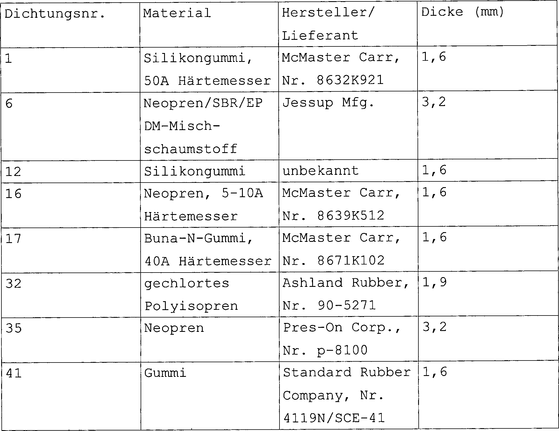
Beispiel 16Example 16

Dieses Beispiel veranschaulicht die Wirkung der verschiedenen Dichtungsmaterialien auf die von einer Person extrahierte Blutmenge.This Example illustrates the effect of the various sealing materials to the amount of blood extracted by a person.

Jeder der vier Freiwilligen wurde 32 Mal von einem modifizierten Medisense-Einschneide-Aufbau, der eine "BD ULTRA-FINE"- Lanzette benutzt, im dorsalen Unterarm getestet. Der Medisense-Einschneide-Aufbau wurde mit einer Öffnung modifiziert, um einem Vakuum zu erlauben, ein Ansaugen durch den Einschneide-Aufbau durchzuführen. Die in diesem Beispiel geprüften Pfeifenköpfe wurden anstelle des gewöhnlichen Pfeifenkopfs auf den Körper eines Medisense-Einschneide-Aufbaus aufgeschraubt. Vakuum (–7,5 psig) wurde fünf Sekunden lang vor dem Einstechen angelegt. Blut wurde nach dem Einstich 30 Sekunden lang bei –7,5 psig mittels Verwendung desselben Pfeifenkopfs, das vor dem Einstich verwendet wurde, entnommen. Die Tiefeneinsetzung der Lanzette war 1,6 mm. Acht verschiedene Pfeifenkopf-Aufbauten wurden entleert. Vier Tests wurden je Pfeifenkopf-Aufbau pro Freiwilliger durchgeführt. Das Blut wurde in Kapillarröhrchen gesammelt. Die entnommene Blutmenge wurde durch Messen der Blutlänge im Röhrchen bestimmt. Die mittlere entnommene Blutmenge für jeden der acht Pfeifenkopf-Aufbauten wird in 41 gezeigt.Each of the four volunteers was tested 32 times in the dorsal forearm by a modified Medisense incision setup using a "BD ULTRA-FINE" lancet. The Medisense incision construction was modified with an opening to allow a vacuum to wick through the incising structure. The pipe heads tested in this example were screwed onto the body of a Medisense incision construction instead of the usual pipe bowl. Vacuum (-7.5 psig) was applied for five seconds prior to piercing. Blood was withdrawn after puncture for 30 seconds at -7.5 psig using the same bowl used prior to puncture. The depth of insertion of the lancet was 1.6 mm. Eight different pipe bowl constructions were emptied. Four tests were performed per pipe head assembly per volunteer. The blood was collected in capillary tubes. The amount of blood removed was determined by measuring the blood length in the tube. The mean amount of blood withdrawn for each of the eight bowl-shaped abutments is in 41 shown.

Für die acht verschiedenen Pfeifenkopf-Aufbauten war der Öffnungsdurchmesser in der unteren Basis (s. Linie "ef" in 32) 10 mm, der Öffnungsdurchmesser in der oberen Basis (s. Linie "cd" in 32) 4 mm, der Rand-zu-Dichtung-Abstand (s. Linie "bg" in 32) 3 mm und die Breite der Dichtungsfläche (s. Linie "hj" in 32) 3,1 mm. Die Pfeifenkopf-Aufbauten unterschieden sich im verwendeten Material für die Pfeifenkopf-Dichtung und in der Dicke der Dichtung. Die acht Varianten des Dichtungsmaterials und ihrer Dicke werden in der Tabelle X aufgelistet.For the eight different pipe bowl constructions the opening diameter was in the lower base (see line "ef" in 32 ) 10 mm, the opening diameter in the upper base (see line "cd" in 32 ) 4 mm, the edge-to-seal distance (see line "bg" in 32 ) 3 mm and the width of the sealing surface (see line "hj" in 32 ) 3.1 mm. The pipe bowl constructions differed in the material used for the pipe head gasket and in the thickness of the gasket. The eight variants of the sealing material and their thickness are listed in Table X.

TABELLE X

Figure 01150001
TABLE X
Figure 01150001

Alle acht verschiedenen Pfeifenkopfdichtungsmaterialien dichteten gut genug an der Haut ab, um die Entnahme eines Durchschnitts zu erlauben, die größer war als 3 μL Blut in 30 Sekunden. Das härteste Material der acht geprüften, Buna N-60A Härtemesser, hatte die höchste Blutentnahmerate. Das Erhöhen der Dichtungsdicke von 1,6 auf 3,2 mm hatte eine geringe Auswirkung auf die in 30 Sekunden entnommene Blutmenge.All eight different pipe head gasket materials sealed well enough on the skin to allow the removal of an average which was bigger as 3 μL Blood in 30 seconds. The hardest Material of the eight tested, Buna N-60A hardness meter, had the highest Blood collection rate. The heightening the seal thickness from 1.6 to 3.2 mm had little effect on the amount of blood taken in 30 seconds.

Beispiel 17Example 17

Dieses Beispiel veranschaulicht die Wirkung einer neuartigen Dichtung auf die Zeit, die benötigt wird, um einer Person Blut zu entnehmen.This Example illustrates the effect of a novel seal on the time it takes is used to draw blood from a person.

Glukosedetektoren in Form von Mehrschichten-Elementen, die, von oben nach unten, die folgenden Schichten umfassen, wurden vorbereitet:

  • (1) Meßgerät-kontaktierbare Schicht
  • (2) Erfassungsschicht
  • (3) Überzugschicht
  • (4) Bluttransportschicht
  • (5) Deckschicht
Glucose detectors in the form of multilayer elements comprising, from top to bottom, the following layers were prepared:
  • (1) Meter-contactable layer
  • (2) acquisition layer
  • (3) coating layer
  • (4) blood transport layer
  • (5) topcoat

Die Anordnung der Schichten wird schematisch in den 21A und 21B gezeigt. Jedoch befindet sich die Überzugschicht, wie in 28 gezeigt, im Wesentlichen in einer Ebene mit der Bluttransportschicht.The arrangement of the layers is schematically shown in FIGS 21A and 21B shown. However, the coating layer is as in 28 shown substantially in one plane with the blood transport layer.

Die Verwendung eines Pfeifenkopfs mit einem Detektor wird in den 34A, 34B, 34C und 34D gezeigt. Der Detektor 1302 wurde unter den Einschneide-Aufbau 1304 gesetzt, wobei die Öffnungen im Detektor mit der Lanzette 1306 ausgerichtet wurden. Der Detektor 1302 wurde zwischen einen Lanzettenanschlag 1308, der eine Öffnung 1309 (gestrichelt gezeigt) enthielt, und einen Pfeifenkopf-Aufbau 1310 gesetzt. Der Pfeifenkopf-Aufbau schloss ein Pfeifenkopf 1311 und eine Dichtung 1312 ein, die die Haut "S" berührte. Der Einschneide-Aufbau 1304 vor der Anlegung des Vakuums wird in 34A gezeigt. Der Pfeifenkopf-Aufbau wurden auf den Unterarm eines Freiwilligen gesetzt. Nach der Anlegung des Vakuums (–7,5 psig) wurde die Haut, wie in 34B gezeigt, nahe an den Detektor oder damit in Kontakt nach oben gedehnt. Das Vakuum wurde über einen Zeitraum (5 Sekunden) angelegt, der ausreicht, damit sich das Blut in der Haut innerhalb des Pfeifenkopfs sammelt. Die Lanzette wurde dann, wie in 34C gezeigt, durch die Öffnungen im Lanzettenanschlag und den Detektor gefeuert. Die Lanzette durchdrang die Haut. Die Lanzette wurde dann, wie in 34D gezeigt, zurückgezogen. Das Blut trat, unterstützt vom Vakuum und vom Hautdehnen, aus der in der Haut gebildeten Öffnung. Das Vakuum unterstützte die Blutentnahme, bis das Blut die Bluttransportschicht erreichte. Das Blut "B" wurde dann an der Bluttransportschicht entlang transportiert, bis es die Erfassungsschicht des Mehrschichten-Elements erreichte. Wenn das Blut die Erfassungsschicht des Mehrschichten-Elements erreichte, wurde ein elektrischer Strom erzeugt. Dieser Strom wurde verwendet, um zu bestimmen, wann das Vakuum aufgehoben wird, und die Haut kam vom Pfeifenkopf weg. Der Detektor konnte dann verwendet werden, um das Blut für einen Analyt wie beispielsweise Glukose zu analysieren.The use of a pipe bowl with a detector is in the 34A . 34B . 34C and 34D shown. The detector 1302 was under the incision construction 1304 set, with the openings in the detector with the lancet 1306 were aligned. The detector 1302 was between a lancet stop 1308 , the one opening 1309 (shown in phantom) and a pipe bowl assembly 1310 set. The pipe bowl construction included a pipe bowl 1311 and a seal 1312 one that touched the skin "S". The incision construction 1304 before the application of the vacuum is in 34A shown. The whistle head-building were placed on the forearm of a volunteer. After application of the vacuum (-7.5 psig) the skin became as in 34B shown near the detector or in contact with it. The vacuum was applied for a period of time (5 seconds) sufficient to collect the blood in the skin inside the bowl. The lancet was then, as in 34C shown fired through the openings in the lancet stop and the detector. The lancet penetrated the skin. The lancet was then, as in 34D shown, withdrawn. The blood, supported by the vacuum and the skin stretching, came out of the opening formed in the skin. The vacuum assisted the blood collection until the blood reached the blood transport layer. The blood "B" was then transported along the blood transport layer until it reached the sensing layer of the multilayer element. When the blood reached the sensing layer of the multilayer element, an electric current was generated. This stream was used to determine when the vacuum was released and the skin came away from the bowl. The detector could then be used to analyze the blood for an analyte such as glucose.

Es sollte angemerkt sein, dass der Lanzettenanschlag eine Option ist. Der Detektor selbst kann verwendet werden, um die Lanzette zu stoppen. Wenn der Detektor verwendet wird, um die Lanzette zu stoppen, ist die Dicke des Detektors wichtig, da sie die Eindringungstiefe der Lanzette bestimmen wird.It It should be noted that the lancet stopper is an option. The detector itself can be used to stop the lancet. If the detector is used to stop the lancet is the thickness of the detector is important as it increases the penetration depth of the Lancet will determine.

Ein pneumatischer Einschneide-Aufbau wurden verwendet, um die Lanzette vorzuschießen. Der pneumatische Einschneide-Aufbau war der Art nach wie der in den 11, 12, 13 und 14 beschriebene.A pneumatic incision assembly was used to prime the lancet. The pneumatic cutting-in structure was of the type like that in the 11 . 12 . 13 and 14 . described

Die verwendete Mehrschichten-Elementart in diesem Beispiel hatte, wie in den 21A und 21B gezeigt, eine Öffnung in der mit dem Meßgerät kontaktierbaren Schicht.The multilayer element type used in this example had, as in the 21A and 21B shown an opening in the contactable with the meter layer.

Zwei Pfeifenkopf-Aufbau-Änderungen wurden in diesem Beispiel verwendet. Die Größe und Struktur beider Pfeifenköpfe in den Pfeifenkopf-Aufbauten waren dieselben wie die des Pfeifenkopfs B aus 35. wenn man davon absieht, dass der Durchmesser der Öffnung in der oberen Basis um 4 mm erhöht wurde. Ein Pfeifenkopf hatte eine ebene Buna N-Dichtung, 40 Härtemesser (s. 32). Das andere Pfeifenkopf hatte eine Dichtung der im Querschnitt in den 21A und 21B gezeigten Art, auf die hiernach als Flex-Dichtung bezeichnet wird. Die Flex-Dichtung berührt einen größeren Hautbereich als es eine ebene Dichtung tut. Die Flex-Dichtung kann veranlassen, dass mehr Haut in den Innenraum des Pfeifenkopfs gebracht wird als dies eine ebene Dichtung zu tun vermag, wenn ein Vakuum angelegt wird. Die Flex-Dichtung wurde aus einem Silikon, 40A Härtemesser, gemacht.Two pipe bowl design changes were used in this example. The size and structure of both pipe bowls in the pipe bowl constructions were the same as those of the pipe bowl B. 35 , apart from the fact that the diameter of the opening in the upper base has been increased by 4 mm. A pipe bowl had a flat Buna N seal, 40 durometer (s. 32 ). The other bowl had a seal of cross section in the 21A and 21B shown type, hereinafter referred to as flex seal. The flex seal touches a larger area of skin than a flat seal does. The flex seal may cause more skin to be placed in the interior of the bowl than a flat seal can do when a vacuum is applied. The flex seal was made from a silicone, 40A durometer.

Die Flex-Dichtung 3020 kann mittels einer mechanischen Anbringung 3024 oder mittels eines Klebers am Pfeifenkopf 3022 befestigt werden. Der Abschnitt 3026 der Flex-Dichtung, der nicht am Pfeifenkopf 3022 angebracht wird, ist in der Lage, sich, wie in 42a gezeigt, zwischen einer ersten Stelle und einer zweiten Stelle, wie in 42b gezeigt, zu bewegen. In der ersten Stellung hängt der nicht befestigte Abschnitt 3026 der Flex-Dichtung 3020, wie in 42a gezeigt, von der unteren Basis 3028 des Pfeifenkopfs 3022 herunter. In der zweiten Stellung berührt der nicht befestigte Abschnitt 3026 der Flex-Dichtung 3028 die untere Basis 3028 des Pfeifenkopfs 3022 so, dass eine Hauptfläche des nicht befestigten Abschnitts der Dichtung, wie in 42b gezeigt, in einem Seite an Seite Kontakt mit der unteren Basis 3028 des Pfeifenkopfs befindet. Die Flex-Dichtung wird aus einem Material gemacht, das einen Reibungskoeffizienten hat, der die Tendenz reduziert, dass die sich damit in Kontakt befindliche Haut rutscht. Die Dichtung sollte flexibel genug sein, um sich zwischen der ersten Stell und der zweiten Stelle bewegen zu können, und fest genug sein, um die Haut in einer unbeweglichen Stellung zu halten. Die Öffnung 3020 in der Flex-Dichtung hat einen größeren Bereich als den Öffnungsbereich 3032 in der unteren Basis 3028 des Pfeifenkopfs 3022, wenn sich die Flex-Dichtung in der ersten Stellung befindet, wie in 42a gezeigt.The flex seal 3020 can by means of a mechanical attachment 3024 or by means of an adhesive on the pipe bowl 3022 be attached. The section 3026 the flex seal that is not on the pipe bowl 3022 is able to, as in 42a shown between a first digit and a second digit, as in 42b shown to move. In the first position hangs the unattached section 3026 the flex seal 3020 , as in 42a shown from the lower base 3028 of the pipe bowl 3022 down. In the second position, the unattached section touches 3026 the flex seal 3028 the lower base 3028 of the pipe bowl 3022 so that a major surface of the unattached portion of the gasket, as in 42b shown in side by side contact with the lower base 3028 of the pipe bowl. The flex seal is made of a material that has a coefficient of friction that reduces the tendency for the skin in contact with it to slip. The gasket should be flexible enough to move between the first and second positions, and strong enough to hold the skin in an immovable position. The opening 3020 in the flex seal has a larger area than the opening area 3032 in the lower base 3028 of the pipe bowl 3022 when the flex seal is in the first position, as in 42a shown.

Während des Betriebs wird die Flex-Dichtung auf die Haut "S" des Patienten gesetzt. Der von der Flex-Dichtung berührte Hautbereich ist größer als der Bereich der Öffnung in der unteren Basis des Pfeifenkopfs. Folglich ist der Anteil der Haut, der in den Pfeifenkopf hochgehoben wird, größer als der Anteil der Haut, der mit einer ebenen Dichtung in den Pfeifenkopf hochgehoben würde. Solchermaßen wäre die Flex-Dichtung für einen Patienten, der unterdurchschnittliche Hautelastizität hat, günstiger.During the Operation, the flex seal on the skin "S" of the Patient set. The skin area touched by the flex seal is larger than the area of the opening in the lower base of the pipe bowl. Consequently, the share of Skin raised in the bowl is larger than the proportion of the skin, with a level seal in the pipe bowl would be lifted. thus that would be Flex seal for a patient who has below-average skin elasticity, cheaper.

Acht Freiwillige wurden allgemein auf die zuvor beschriebene Weise am dorsalen Unterarm getestet. In den vorherigen Beispielen wurde der Pfeifenkopf-Aufbau betätigt, indem er seitlich oder in Richtung zu oder weg von der Haut bewegt wurde. In diesem Beispiel wurde der Pfeifenkopf-Aufbau nicht bewegt, nachdem er auf die Haut gesetzt wurde. Acht Freiwillige wurden achtmal mittels Verwendung der ebenen Dichtungs- und Flex-Dichtungsanordnungen für insgesamt 16 Tests pro Freiwilliger geprüft. Die Zeit zum Füllen des Detektors nach dem Einstich wurde aufgezeichnet. Der Detektor wurde als gefüllt angesehen, wenn ein Strom von 1,5 μA erzeugt wurde. Das Vakuum wurde danach aufgehoben. Die durchschnittliche Zeit, die benötigt wurde, damit der Strom 1,5 μA erreichte, war für die Flex-Dichtung 14,9 Sekunden. Die durchschnittliche Zeit, damit der Strom 1,5 μA erreichte, war für die ebene Dichtung 17,9 Sekunden.Eight volunteers were generally tested on the dorsal forearm in the manner previously described. In the previous examples, the bowl assembly was actuated by being moved laterally or toward or away from the skin. In this example, the bowl assembly was not moved after it had been placed on the skin. Eight volunteers were tested eight times using the flat seal and flex seal assemblies for a total of 16 tests per volunteer. The time to fill the detector after the puncture was recorded. The detector was considered filled when a current of 1.5 μA was generated. The vacuum was lifted afterwards. The average time required for the current to reach 1.5 μA was 14.9 seconds for the Flex seal. The average time for the current to reach 1.5 μA was 17.9 seconds for the planar seal.

Der Pfeifenkopf, der die Flex-Dichtung benutzte, brauchte weniger Zeit zum Füllen des Detektors als der Pfeifenkopf, das eine ebene Dichtung benutzte. Überdies wurde der Umgang mit dem Pfeifenkopf-Aufbau vermieden.Of the Pipe head using the flex seal took less time to fill of the detector as the pipe head, which used a plane seal. moreover the handling of the pipe bowl construction was avoided.

Beispiel 18Example 18

Dieses Beispiel zeigt, dass die in den 44A und 44B gezeigte Vorrichtung erfolgreich verwendet werden kann, um Blut in einer annehmbar kurzen Zeitspanne in Mengen zu erhalten, die für die Analyse ausreicht.This example shows that in the 44A and 44B can be successfully used to obtain blood in a reasonably short period of time in amounts sufficient for analysis.

Die in den 44A und 44B gezeigte Blutentnahmevorrichtung wurde mit einer "Becton-Dickinson ULTRA-FINE"-Lanzette in einem pneumatischen Lanzetten-Aufbau der in den 1119 dargestellten Art ausgestattet. Die Blutentnahmevorrichtung wurde auch mit einem Glukosedetektor ausgestattet, der eine von einer Masche bedeckte Durchmesseröffnung von 2,0 mm hat. 29 Freiwillige wurden in diesem Beispiel verwendet, wobei der dorsale Unterarm eines jeden Freiwilligen zwei unabhängigen Entnahmeverfahren unterzogen wurde. Für jedes Verfahren wurde die Blutentnahmevorrichtung auf den Unterarm des Freiwilligen gesetzt, und nachdem jede Person fünf Sekunden lang einem Vakuum von annähernd –7,5 psig ausgesetzt wurde, wurde sein/ihr Unterarm (dorsaler Unterarm) eingestochen. Nach dem Einstich wurde Blut entnommen, und, wenn genügend Blut gesammelt war, das Vakuum aufgehoben und die Blutentnahmevorrichtung von der Haut der Person weggenommen. Dieses Verfahren wurde für jede Person insgesamt fünfmal wiederholt. Vor jeder Entnahme wurden eine neue Lanzette und ein Glukosedetektor in die Blutentnahmevorrichtung gesteckt.The in the 44A and 44B was shown with a "Becton-Dickinson ULTRA-FINE" lancet in a pneumatic lancet assembly in the 11 - 19 equipped type. The blood collection device was also equipped with a glucose detector having a mesh-covered diameter opening of 2.0 mm. Twenty-nine volunteers were used in this example with the dorsal forearm of each volunteer subjected to two independent sampling procedures. For each procedure, the blood sampling device was placed on the volunteer's forearm, and after each person was exposed to a vacuum of approximately -7.5 psig for five seconds, his / her forearm (dorsal forearm) was pierced. After the puncture, blood was withdrawn and, when sufficient blood was collected, the vacuum was released and the blood collection device was removed from the person's skin. This procedure was repeated five times for each person. Before each collection, a new lancet and a glucose detector were inserted into the blood collection device.

Die Zeit, damit der Glukosedetektor genug Blut entnahm, um eine Analyse durchzuführen, wurde aufgezeichnet. Es wurde befunden, dass der Glukosedetektor genug Blut gesammelt hatte, wenn ein Strom von 1,5 μA erzeugt wurde. Die Blutentnahmeergebnisse werden in 47 dargelegt. Die graphisch in 47 dargestellten Rohdaten für jeden Freiwilligen werden in der Tabelle XI gezeigt.The time for the glucose detector to draw enough blood to perform an analysis was recorded. It was found that the glucose detector had collected enough blood when a current of 1.5 μA was generated. The blood collection results will be in 47 explained. The graphically in 47 raw data presented for each volunteer are shown in Table XI.

TABELLE XI

Figure 01200001
TABLE XI
Figure 01200001

Die in 47 dargestellten Daten zeigen, dass für über 35% der Einstiche innerhalb von fünf Sekunden genug Blut entnommen war, um eine Analyse durchzuführen. Mit Ausnahme eines Glukosedetektors, der schlecht funktionierte (Freiwilliger 25, Versuch 2) entnahmen die Glukosedetektoren bei etwa 95% der Einstiche in 40 Sekunden oder weniger genug Blut für die Analyse. Für die übrigen Einstiche wurden die Tests nach 40 Sekunden gestoppt. Hinsichtlich dieser Einstiche, für die in 40 Sekunden oder weniger genug Blut entnommen wurde, betrug die durchschnittliche Zeit zur Entnahme von genug Blut 8,2 Sekunden.In the 47 The data shown in the figure shows that for more than 35% of the punctures, enough blood was taken within five seconds to perform an analysis. With the exception of a glucose detector that performed poorly (volunteer 25, experiment 2), about 95% of the punctures in 40 seconds or less, the glucose detectors collected enough blood for analysis. For the remaining punctures, the tests were stopped after 40 seconds. With regard to these punctures, for which enough blood was drawn in 40 seconds or less, the average time to take enough blood was 8.2 seconds.

Beispiel 19Example 19

Dieses Beispiel zeigt, dass die in den 43A bis 43C gezeigte Vorrichtung erfolgreich verwendet werden kann, um Blut in einer annehmbar kurzen Zeitspanne in Mengen zu erhalten, die für die Analyse ausreicht.This example shows that in the 43A to 43C can be successfully used to obtain blood in a reasonably short period of time in amounts sufficient for analysis.

Die in den 43A bis 43C gezeigte Blutentnahmevorrichtung wurde mit einer "BD ULTRA-FINE"-Lanzette in einem pneumatischen Lanzetten-Aufbau der in den 1119 dargestellten Art ausgestattet. Die Blutentnahmevorrichtung wurde auch mit einem Glukosedetektor ausgestattet, der eine von einer Masche bedeckte Durchmesseröffnung von 2,0 mm hat. 15 Freiwillige wurden in diesem Beispiel verwendet, wobei der dorsale Unterarm eines jeden Freiwilligen vier unabhängigen Entnahmeverfahren unterzogen wurde. Für jedes Verfahren wurde die Blutentnahmevorrichtung auf den Unterarm des Freiwilligen gesetzt, und nachdem jede Person etwa fünf Sekunden lang einem Vakuum von annähernd –7,5 psig ausgesetzt wurde, wurde sein/ihr Unterarm (dorsaler Unterarm) eingestochen. Nach dem Einstich wurde Blut entnommen, und, wenn genügend Blut entnommen war, das Vakuum aufgehoben und die Blutentnahmevorrichtung von der Haut der Person weggenommen. Dieses Verfahren wurde für jede Person insgesamt viermal wiederholt. Vor jeder Entnahme wurden eine neue Lanzette und ein Glukosedetektor in die Blutentnahmevorrichtung gesteckt.The in the 43A to 43C was shown with a "BD ULTRA-FINE" lancet in a pneumatic lancet assembly in the 11 - 19 equipped type. The blood collection device was also equipped with a glucose detector having a mesh-covered diameter opening of 2.0 mm. Fifteen volunteers were used in this example with the dorsal forearm of each volunteer undergoing four independent retrieval procedures. For each procedure, the blood sampling device was placed on the volunteer's forearm, and after each person was exposed to a vacuum of approximately -7.5 psig for about five seconds, his / her forearm (dorsal forearm) was pierced. After the puncture, blood was withdrawn and, when sufficient blood was drawn, the vacuum was released and the blood collection device was removed from the person's skin. This procedure was repeated four times for each person in total. Before each collection, a new lancet and a glucose detector were inserted into the blood collection device.

Die Zeit, damit der Glukosedetektor genug Blut entnahm, um eine Analyse durchzuführen, wurde aufgezeichnet. Es wurde befunden, dass der Glukosedetektor genug Blut gesammelt hatte, wenn ein Strom von 1,5 μA erzeugt wurde. Die Blutentnahmeergebnisse werden in 48 dargelegt.The time for the glucose detector to draw enough blood to perform an analysis was recorded. It was found that the glucose detector had collected enough blood when a current of 1.5 μA was generated. The blood collection results will be in 48 explained.

Die in 48 dargestellten Daten zeigen, dass für etwa 45% der Einstiche innerhalb von fünf Sekunden genug Blut entnommen war, um eine Analyse durchzuführen. Die Glukosedetek toren entnahmen bei etwa 97% der Einstiche in 40 Sekunden oder weniger genug Blut für die Analyse. Für die übrigen Einstiche wurden die Tests nach 40 Sekunden gestoppt. Hinsichtlich dieser Einstiche, für die in 40 Sekunden oder weniger genug Blut entnommen wurde, betrug die durchschnittliche Zeit zur Entnahme von genug Blut 7,0 Sekunden.In the 48 The data presented shows that for approximately 45% of the punctures, enough blood was taken within five seconds to perform an analysis. The glucose sensors collected enough blood for analysis in about 97% of the punctures in 40 seconds or less. For the remaining punctures, the tests were stopped after 40 seconds. With regard to these punctures, for which enough blood was drawn in 40 seconds or less, the average time to take enough blood was 7.0 seconds.

Beispiel 20Example 20

Dieses Beispiel zeigt, dass die in den 45A bis 45E gezeigte Vorrichtung erfolgreich verwendet werden kann, um Blut in einer annehmbar kurzen Zeitspanne in Mengen zu erhalten, die für die Analyse ausreicht.This example shows that in the 45A to 45E can be successfully used to obtain blood in a reasonably short period of time in amounts sufficient for analysis.

Die in den 45A bis 45c gezeigte Blutentnahmevorrichtung wurde mit einer "BD ULTRA-FINE"-Lanzette in einem pneumatischen Lanzetten-Aufbau der in den 1119 dargestellten Art ausgestattet. Die Blutentnahmevorrichtung wurde auch mit einem Glukosedetektor ausgestattet, der an einem Ende des Detektors einen halbkreisförmigen Schlitz eines Durchmessers von 2,0 mm hat, der mit der Masche bedeckt ist. 29 Freiwillige wurden in diesem Beispiel verwendet, wobei der dorsale Unterarm eines jeden Freiwilligen zwei unabhängigen Entnahmeverfahren unterzogen wurde. Für jedes Verfahren wurde die Blutentnahmevorrichtung auf den Unterarm des Freiwilligen gesetzt, und nachdem jede Person etwa fünf Sekunden lang einem Vakuum von annähernd –7,5 psig ausgesetzt wurde, wurde sein/ihr Unterarm (dorsaler Unterarm) eingestochen. 50 Millisekunden nachdem die Lanzette ausgelöst wurde, wurde der bewegliche Vorsprung ausgelöst und der Glukosedetektor näher an die eingeritzte Öffnung in der Haut der Person bewegt. Nach dem Einstich wurde Blut entnommen, und, wenn genügend Blut entnommen war, das Vakuum aufgehoben und die Blutentnahmevorrichtung von der Haut der Person weggenommen. Dieses Verfahren wurde für jede Person insgesamt zweimal wiederholt. Vor jeder Entnahme wurden eine neue Lanzette und ein Glukosedetektor in die Blutentnahmevorrichtung gesteckt.The in the 45A to 45c was shown with a "BD ULTRA-FINE" lancet in a pneumatic lancet assembly in the 11 - 19 equipped type. The blood collection device was also equipped with a glucose detector having at one end of the detector a semicircular slit of diameter 2.0 mm covered with the mesh. Twenty-nine volunteers were used in this example with the dorsal forearm of each volunteer subjected to two independent sampling procedures. For each procedure, the blood sampling device was placed on the volunteer's forearm, and after each person was exposed to a vacuum of approximately -7.5 psig for about five seconds, his / her forearm (dorsal forearm) was pierced. 50 milliseconds after the lancet was triggered, the movable projection was released and the glucose detector moved closer to the incised opening in the person's skin. After the puncture, blood was withdrawn and, when sufficient blood was drawn, the vacuum was released and the blood collection device was removed from the person's skin. This procedure was repeated twice for each person in total. Before each collection, a new lancet and a glucose detector were inserted into the blood collection device.

Die Zeit, damit der Glukosedetektor genug Blut entnahm, um eine Analyse durchzuführen, wurde aufgezeichnet. Es wurde befunden, dass der Glukosedetektor genug Blut gesammelt hatte, wenn ein Strom von 1,5 μA erzeugt wurde. Die Blutentnahmeergebnisse werden in 49 dargelegt.The time for the glucose detector to draw enough blood to perform an analysis was recorded. It was found that the glucose detector had collected enough blood when a current of 1.5 μA was generated. The blood collection results will be in 49 explained.

Die in 49 dargestellten Daten zeigen, dass für über 55% der Einstiche innerhalb von 5 Sekunden genug Blut entnommen wurde, um eine Analyse durchzuführen. Zwei der Glukosedetektoren überstiegen infolge von Hardware- oder Software-Problemen nicht den Auslöserstrom von 1,5 μA. Zwei der Glukosedetektoren bewegten sich infolge eines unbekannten Problems nicht und berührten nicht die Haut. Diese vier Einstiche ausgenommen, entnahmen die Glukosedetektor für 91% der übrigen Einstiche in 40 Sekunden oder weniger genug Blut für die Analyse. Für die übrigen Einstiche wurden die Tests nach 40 Sekunden gestoppt. Hinsichtlich jener Einstiche, für die in 40 Sekunden oder weniger genug Blut entnommen wurde, betrug die durchschnittliche Zeit zur Entnahme von genug Blut 6,8 Sekunden.In the 49 The data presented above shows that for more than 55% of the punctures, enough blood has been taken within 5 seconds to perform an analysis. Two of the glucose detectors did not exceed the trigger current of 1.5 μA due to hardware or software problems. Two of the glucose detectors did not move due to an unknown problem and did not touch the skin. Excluding these four punctures, the glucose detector extracted enough blood for analysis for 91% of the remaining punctures in 40 seconds or less. For the remaining punctures, the tests were stopped after 40 seconds. With regard to those punctures for which enough blood was taken in 40 seconds or less, the Average time to take enough blood 6.8 seconds.

Verschiedene Modifikationen und Änderungen dieser Erfindung werden den Fachleuten auf dem Gebiet ersichtlich sein, ohne sich vom Schutzumfang dieser Erfindung zu lösen, und es sollte klar sein, dass diese Erfindung nicht ungewollt auf die hierin dargelegten veranschaulichenden Ausführungsformen beschränkt ist.Various Modifications and changes of this invention will be apparent to those skilled in the art without departing from the scope of this invention, and It should be clear that this invention is not unintentional on the is limited to illustrative embodiments set forth herein.

Claims (10)

Ein Gerät, das zum Erhalten einer Blutprobe geeignet ist, wobei das Gerät folgendes umfasst: (a) ein Gehäuse, worin das Gehäuse weiterhin eine Elektronik enthält, die programmierte Befehle zum Ein- und Ausschalten der Vakuumpumpe hat, damit der gewünschte Vakuumpegel aufrechterhalten bleibt, (b) eine Vorrichtung zum Bilden einer nicht versperrten Öffnung in einem Hautbereich, aus dem die Probe entnommen werden soll; und (c) eine Vakuumpumpe zur Entnahme der Probe aus der nicht versperrten Öffnung im Hautbereich, wobei die Vakuumpumpe in der Lage ist, ein- und ausgeschaltet zu werden, um einen gewünschten Vakuumpegel beizubehalten.A machine, suitable for obtaining a blood sample, the device includes: (a) a housing, wherein the housing furthermore contains electronics, the programmed commands for switching the vacuum pump on and off has, so that the desired Vacuum level is maintained, (b) a device for Forming an unlocked opening in a skin area from which the sample is to be taken; and (C) a vacuum pump for taking the sample from the unobstructed opening in Skin area, where the vacuum pump is able to turn on and off to become a desired one Maintain vacuum level. Das Gerät nach Anspruch 1, worin die Vorrichtung zum Bilden der nicht versperrten Öffnung eine in einem Einschneide-Aufbau angeordnete Lanzette umfasst.The device The device according to claim 1, wherein the means for forming the unobstructed opening comprises in a single incision construction arranged lancet includes. Das Gerät nach Anspruch 2, worin der Einschneide-Aufbau einen Pfeifenkopf umfasst, der eine Dichtung hat, wodurch von der Vakuumpumpe durch den Einschneide-Aufbau ein Vakuum gebildet werden kann.The device according to claim 2, wherein the incising structure is a bowl comprising, which has a seal, whereby by the vacuum pump through the incising construction can be made a vacuum. Das Gerät nach Anspruch 1, worin die Lanzette in der Lage ist, zurückgezogen zu werden, nachdem sie die nicht versperrte Öffnung in der Haut bildet.The device according to claim 1, wherein the lancet is capable of being withdrawn after it forms the unobstructed opening in the skin. Das Gerät nach Anspruch 1, worin die Vorrichtung zum Bilden der nicht versperrten Öffnung ein Laser ist.The device according to claim 1, wherein the device for forming the unobstructed opening a Laser is. Das Gerät nach Anspruch 1, worin die Vorrichtung zum Bilden der nicht versperrten Öffnung ein Fluidstrahl ist.The device according to claim 1, wherein the device for forming the unobstructed opening a Fluid jet is. Das Gerät nach Anspruch 1, das weiterhin ein HeizelementThe device according to claim 1, further comprising a heating element Das Gerät nach Anspruch 1, das weiterhin einen Glukosedetektor umfasst.The device according to claim 1, further comprising a glucose detector. Das Gerät nach Anspruch 1, worin der Glukosedetektor weiterhin ein Biosensor ist.The device according to claim 1, wherein the glucose detector further comprises a biosensor is. Das Gerät nach Anspruch 1, worin der Glukosedetektor ein Reflektometer ist.The device according to claim 1, wherein the glucose detector is a reflectometer.
DE69733486T 1996-12-06 1997-12-04 BLOOD GENERATION DEVICE FOR DIAGNOSTIC TESTS Expired - Lifetime DE69733486T2 (en)

Applications Claiming Priority (5)

Application Number Priority Date Filing Date Title
US759698 1996-12-06
US08/759,698 US6063039A (en) 1996-12-06 1996-12-06 Method and apparatus for obtaining blood for diagnostic tests
US3639597P 1997-01-24 1997-01-24
US36395P 1997-01-24
PCT/US1997/022618 WO1998024366A2 (en) 1996-12-06 1997-12-04 Method and apparatus for obtaining blood for diagnostic tests

Publications (2)

Publication Number Publication Date
DE69733486D1 DE69733486D1 (en) 2005-07-14
DE69733486T2 true DE69733486T2 (en) 2006-03-23

Family

ID=26713137

Family Applications (3)

Application Number Title Priority Date Filing Date
DE69739426T Expired - Lifetime DE69739426D1 (en) 1996-12-06 1997-12-04 Arrangement for providing an opening in the skin of a patient by means of a lancet
DE69739278T Expired - Lifetime DE69739278D1 (en) 1996-12-06 1997-12-04 Nose piece suitable for a blood sampling device
DE69733486T Expired - Lifetime DE69733486T2 (en) 1996-12-06 1997-12-04 BLOOD GENERATION DEVICE FOR DIAGNOSTIC TESTS

Family Applications Before (2)

Application Number Title Priority Date Filing Date
DE69739426T Expired - Lifetime DE69739426D1 (en) 1996-12-06 1997-12-04 Arrangement for providing an opening in the skin of a patient by means of a lancet
DE69739278T Expired - Lifetime DE69739278D1 (en) 1996-12-06 1997-12-04 Nose piece suitable for a blood sampling device

Country Status (11)

Country Link
US (7) US6027459A (en)
EP (5) EP1112717A1 (en)
JP (6) JP3424935B2 (en)
CN (5) CN1524494A (en)
AT (3) ATE423507T1 (en)
AU (1) AU736675B2 (en)
CA (2) CA2272333C (en)
DE (3) DE69739426D1 (en)
ES (1) ES2244017T3 (en)
NO (1) NO992730L (en)
WO (1) WO1998024366A2 (en)

Families Citing this family (729)

* Cited by examiner, † Cited by third party
Publication number Priority date Publication date Assignee Title
US7666150B2 (en) * 1996-05-17 2010-02-23 Roche Diagnostics Operations, Inc. Blood and interstitial fluid sampling device
US7235056B2 (en) 1996-05-17 2007-06-26 Amira Medical Body fluid sampling device and methods of use
US7828749B2 (en) 1996-05-17 2010-11-09 Roche Diagnostics Operations, Inc. Blood and interstitial fluid sampling device
EP1579814A3 (en) 1996-05-17 2006-06-14 Roche Diagnostics Operations, Inc. Methods and apparatus for sampling and analyzing body fluid
US20020010406A1 (en) 1996-05-17 2002-01-24 Douglas Joel S. Methods and apparatus for expressing body fluid from an incision
US6332871B1 (en) 1996-05-17 2001-12-25 Amira Medical Blood and interstitial fluid sampling device
DE69722414T2 (en) 1996-07-03 2004-05-19 Altea Therapeutics Corp. MULTIPLE MECHANICAL MICROPERFORATION OF SKIN OR MUCOSA
US6027459A (en) * 1996-12-06 2000-02-22 Abbott Laboratories Method and apparatus for obtaining blood for diagnostic tests
US6527716B1 (en) 1997-12-30 2003-03-04 Altea Technologies, Inc. Microporation of tissue for delivery of bioactive agents
DE69809391T2 (en) 1997-02-06 2003-07-10 Therasense Inc SMALL VOLUME SENSOR FOR IN-VITRO DETERMINATION
US7899511B2 (en) 2004-07-13 2011-03-01 Dexcom, Inc. Low oxygen in vivo analyte sensor
US9155496B2 (en) 1997-03-04 2015-10-13 Dexcom, Inc. Low oxygen in vivo analyte sensor
US6706000B2 (en) * 1997-11-21 2004-03-16 Amira Medical Methods and apparatus for expressing body fluid from an incision
US5964718A (en) 1997-11-21 1999-10-12 Mercury Diagnostics, Inc. Body fluid sampling device
US6155992A (en) * 1997-12-02 2000-12-05 Abbott Laboratories Method and apparatus for obtaining interstitial fluid for diagnostic tests
US6071294A (en) * 1997-12-04 2000-06-06 Agilent Technologies, Inc. Lancet cartridge for sampling blood
US6036924A (en) 1997-12-04 2000-03-14 Hewlett-Packard Company Cassette of lancet cartridges for sampling blood
JP2000014662A (en) * 1998-01-22 2000-01-18 Terumo Corp Humor examination device
US6103033A (en) 1998-03-04 2000-08-15 Therasense, Inc. Process for producing an electrochemical biosensor
US6391005B1 (en) * 1998-03-30 2002-05-21 Agilent Technologies, Inc. Apparatus and method for penetration with shaft having a sensor for sensing penetration depth
JP3382853B2 (en) * 1998-04-09 2003-03-04 松下電器産業株式会社 Body fluid testing device
US6949816B2 (en) 2003-04-21 2005-09-27 Motorola, Inc. Semiconductor component having first surface area for electrically coupling to a semiconductor chip and second surface area for electrically coupling to a substrate, and method of manufacturing same
US6175752B1 (en) 1998-04-30 2001-01-16 Therasense, Inc. Analyte monitoring device and methods of use
US9066695B2 (en) 1998-04-30 2015-06-30 Abbott Diabetes Care Inc. Analyte monitoring device and methods of use
US8346337B2 (en) 1998-04-30 2013-01-01 Abbott Diabetes Care Inc. Analyte monitoring device and methods of use
US8688188B2 (en) 1998-04-30 2014-04-01 Abbott Diabetes Care Inc. Analyte monitoring device and methods of use
US8974386B2 (en) 1998-04-30 2015-03-10 Abbott Diabetes Care Inc. Analyte monitoring device and methods of use
US8465425B2 (en) 1998-04-30 2013-06-18 Abbott Diabetes Care Inc. Analyte monitoring device and methods of use
US8480580B2 (en) 1998-04-30 2013-07-09 Abbott Diabetes Care Inc. Analyte monitoring device and methods of use
US7037277B1 (en) 1998-07-21 2006-05-02 Spectrx, Inc. System and method for fluid management in a continuous fluid collection and sensor device
US6187000B1 (en) * 1998-08-20 2001-02-13 Endius Incorporated Cannula for receiving surgical instruments
US6338790B1 (en) 1998-10-08 2002-01-15 Therasense, Inc. Small volume in vitro analyte sensor with diffusible or non-leachable redox mediator
US6591125B1 (en) * 2000-06-27 2003-07-08 Therasense, Inc. Small volume in vitro analyte sensor with diffusible or non-leachable redox mediator
ATE408372T1 (en) * 1999-01-04 2008-10-15 Terumo Corp LANDZET ARRANGEMENT FOR COLLECTION AND DETECTION OF BODY FLUID
US6210420B1 (en) 1999-01-19 2001-04-03 Agilent Technologies, Inc. Apparatus and method for efficient blood sampling with lancet
US6565738B1 (en) 1999-01-28 2003-05-20 Abbott Laboratories Diagnostic test for the measurement of analyte in abiological fluid
US6925317B1 (en) * 1999-06-11 2005-08-02 Spectrx, Inc. Integrated alignment devices, system, and methods for efficient fluid extraction, substance delivery and other applications
DE19926931A1 (en) * 1999-06-14 2000-12-21 Roche Diagnostics Gmbh Method and device for checking the liquid absorption of a test layer of an analysis element
US6558402B1 (en) * 1999-08-03 2003-05-06 Becton, Dickinson And Company Lancer
US20030078499A1 (en) * 1999-08-12 2003-04-24 Eppstein Jonathan A. Microporation of tissue for delivery of bioactive agents
US6234980B1 (en) * 1999-08-27 2001-05-22 Medcare Medical Group, Inc. Needlestick first response kit and method of using same
JP4210782B2 (en) * 1999-10-13 2009-01-21 アークレイ株式会社 Blood sampling position indicator
US6283982B1 (en) * 1999-10-19 2001-09-04 Facet Technologies, Inc. Lancing device and method of sample collection
JP3985022B2 (en) * 1999-11-08 2007-10-03 アークレイ株式会社 Body fluid measuring device and insertion body used by being inserted into the body fluid measuring device
TW416005B (en) * 1999-11-11 2000-12-21 Apex Biotechnology Corp Biosensor with multiple sampling ways
EP1229825B1 (en) * 1999-11-19 2012-06-20 SpectRx, Inc. Tissue interface device
DE10003507B4 (en) * 2000-01-27 2004-06-03 Knoll, Meinhard, Prof. Dr. Device and method for the removal of liquids from the body's own tissue and determination of substance concentrations in this liquid
US6706159B2 (en) * 2000-03-02 2004-03-16 Diabetes Diagnostics Combined lancet and electrochemical analyte-testing apparatus
DE10010694A1 (en) * 2000-03-04 2001-09-06 Roche Diagnostics Gmbh Lancet including tipped needle with body surrounding tip
US6612111B1 (en) * 2000-03-27 2003-09-02 Lifescan, Inc. Method and device for sampling and analyzing interstitial fluid and whole blood samples
US6623501B2 (en) 2000-04-05 2003-09-23 Therasense, Inc. Reusable ceramic skin-piercing device
US7780610B2 (en) 2000-05-01 2010-08-24 Terumo Kabushiki Kaisha Component measuring instrument and chip
US20060211931A1 (en) * 2000-05-02 2006-09-21 Blank Thomas B Noninvasive analyzer sample probe interface method and apparatus
US7519406B2 (en) * 2004-04-28 2009-04-14 Sensys Medical, Inc. Noninvasive analyzer sample probe interface method and apparatus
US7606608B2 (en) * 2000-05-02 2009-10-20 Sensys Medical, Inc. Optical sampling interface system for in-vivo measurement of tissue
US6506168B1 (en) * 2000-05-26 2003-01-14 Abbott Laboratories Apparatus and method for obtaining blood for diagnostic tests
DE10026172A1 (en) 2000-05-26 2001-11-29 Roche Diagnostics Gmbh Body fluid withdrawal system
DE10026170A1 (en) 2000-05-26 2001-12-06 Roche Diagnostics Gmbh Body fluid withdrawal system
EP1787583B1 (en) * 2000-06-09 2012-02-01 Diabetes Diagnostics, Inc. Cap for a lancing drive
US6540675B2 (en) * 2000-06-27 2003-04-01 Rosedale Medical, Inc. Analyte monitor
WO2002002433A2 (en) * 2000-07-03 2002-01-10 Kodiak Technologies, Inc. Thermal container with data monitoring system
US6833110B2 (en) * 2000-07-20 2004-12-21 Hypoguard Limited Test member
EP1304075B1 (en) * 2000-07-26 2009-01-21 Terumo Kabushiki Kaisha Body fluid composition measuring apparatus
US6555061B1 (en) * 2000-10-05 2003-04-29 Lifescan, Inc. Multi-layer reagent test strip
DE10053974A1 (en) 2000-10-31 2002-05-29 Roche Diagnostics Gmbh Blood collection system
DE10057832C1 (en) * 2000-11-21 2002-02-21 Hartmann Paul Ag Blood analysis device has syringe mounted in casing, annular mounting carrying needles mounted behind test strip and being swiveled so that needle can be pushed through strip and aperture in casing to take blood sample
US8641644B2 (en) * 2000-11-21 2014-02-04 Sanofi-Aventis Deutschland Gmbh Blood testing apparatus having a rotatable cartridge with multiple lancing elements and testing means
US6560471B1 (en) 2001-01-02 2003-05-06 Therasense, Inc. Analyte monitoring device and methods of use
EP2361556A2 (en) 2001-01-12 2011-08-31 ARKRAY, Inc. Lancing device, method of making lancing device, pump mechanism and sucking device
BR0206604A (en) * 2001-01-22 2004-02-17 Hoffmann La Roche Lancet device that has capillary action
US6572745B2 (en) 2001-03-23 2003-06-03 Virotek, L.L.C. Electrochemical sensor and method thereof
US6576102B1 (en) 2001-03-23 2003-06-10 Virotek, L.L.C. Electrochemical sensor and method thereof
US7310543B2 (en) * 2001-03-26 2007-12-18 Kumetrix, Inc. Silicon microprobe with integrated biosensor
CN100339044C (en) * 2001-03-29 2007-09-26 因弗内斯医疗有限公司 Integrated measuring apparatus for testing samples
US7041468B2 (en) 2001-04-02 2006-05-09 Therasense, Inc. Blood glucose tracking apparatus and methods
US6783502B2 (en) * 2001-04-26 2004-08-31 Phoenix Bioscience Integrated lancing and analytic device
DE10121883A1 (en) * 2001-05-05 2002-11-07 Roche Diagnostics Gmbh Blood Collection system
US6503209B2 (en) * 2001-05-18 2003-01-07 Said I. Hakky Non-invasive focused energy blood withdrawal and analysis system
JP3934107B2 (en) * 2001-06-08 2007-06-20 エフ ホフマン−ラ ロッシュ アクチェン ゲゼルシャフト Test strip for collecting body fluid and method for collecting body fluid
US20020188223A1 (en) * 2001-06-08 2002-12-12 Edward Perez Devices and methods for the expression of bodily fluids from an incision
DE60229988D1 (en) * 2001-06-08 2009-01-02 Roche Diagnostics Gmbh Removal device for Körperflussigkeiten
US8337419B2 (en) 2002-04-19 2012-12-25 Sanofi-Aventis Deutschland Gmbh Tissue penetration device
WO2002100253A2 (en) * 2001-06-12 2002-12-19 Pelikan Technologies, Inc. Blood sampling device with diaphragm actuated lancet
US7025774B2 (en) 2001-06-12 2006-04-11 Pelikan Technologies, Inc. Tissue penetration device
DE60234598D1 (en) 2001-06-12 2010-01-14 Pelikan Technologies Inc SELF-OPTIMIZING LANZET DEVICE WITH ADAPTANT FOR TEMPORAL FLUCTUATIONS OF SKIN PROPERTIES
US7749174B2 (en) 2001-06-12 2010-07-06 Pelikan Technologies, Inc. Method and apparatus for lancet launching device intergrated onto a blood-sampling cartridge
US20070100255A1 (en) * 2002-04-19 2007-05-03 Pelikan Technologies, Inc. Method and apparatus for body fluid sampling and analyte sensing
US9226699B2 (en) 2002-04-19 2016-01-05 Sanofi-Aventis Deutschland Gmbh Body fluid sampling module with a continuous compression tissue interface surface
EP1404234B1 (en) 2001-06-12 2011-02-09 Pelikan Technologies Inc. Apparatus for improving success rate of blood yield from a fingerstick
CA2448681C (en) * 2001-06-12 2014-09-09 Pelikan Technologies, Inc. Integrated blood sampling analysis system with multi-use sampling module
ATE485766T1 (en) 2001-06-12 2010-11-15 Pelikan Technologies Inc ELECTRICAL ACTUATING ELEMENT FOR A LANCET
US7682318B2 (en) * 2001-06-12 2010-03-23 Pelikan Technologies, Inc. Blood sampling apparatus and method
US9795747B2 (en) 2010-06-02 2017-10-24 Sanofi-Aventis Deutschland Gmbh Methods and apparatus for lancet actuation
US7981056B2 (en) 2002-04-19 2011-07-19 Pelikan Technologies, Inc. Methods and apparatus for lancet actuation
WO2003088851A1 (en) 2001-06-12 2003-10-30 Pelikan Technologies, Inc. Tissue penetration device
US9427532B2 (en) 2001-06-12 2016-08-30 Sanofi-Aventis Deutschland Gmbh Tissue penetration device
US7776608B2 (en) * 2001-07-09 2010-08-17 Bayer Healthcare Llc Volume meter testing device and method of use
CN1273075C (en) * 2001-07-13 2006-09-06 爱科来株式会社 Analyzing apparatus, piercing element integrally installed body for temperature measuring device with analyzing apparatus, and body fluid sampling apparatus
WO2003007819A1 (en) * 2001-07-19 2003-01-30 Arkray, Inc. Piercing device
DE10134650B4 (en) 2001-07-20 2009-12-03 Roche Diagnostics Gmbh System for taking small amounts of body fluid
DE10193213T8 (en) * 2001-07-27 2013-04-25 Arkray, Inc. analytical tool
US20030032874A1 (en) 2001-07-27 2003-02-13 Dexcom, Inc. Sensor head for use with implantable devices
EP1413249B1 (en) * 2001-08-03 2013-10-09 ARKRAY, Inc. Installation body for body fluid sampling apparatus and method of manufacturing the apparatus
AU2002300223B2 (en) * 2001-08-13 2008-12-11 Bayer Corporation Mechanical Mechanism for a Blood Glucose Sensor Dispensing Instrument
US20040116830A1 (en) * 2001-08-24 2004-06-17 Trudeau William M Blood testing deivce
DE10142232B4 (en) * 2001-08-29 2021-04-29 Roche Diabetes Care Gmbh Process for the production of an analytical aid with a lancet and test element
JP2005501591A (en) * 2001-08-29 2005-01-20 エフ ホフマン−ラ ロッシュ アクチェン ゲゼルシャフト Exudation method and structure for use in sampling body fluid
DE60144582D1 (en) * 2001-09-19 2011-06-16 Terumo Corp DEVICE FOR MEASURING COMPONENTS AND CHIPS
MXPA04002687A (en) * 2001-09-24 2004-06-18 Atsuo F Fukunaga Breathing circuits having unconventional respiratory conduits and systems and methods for optimising utilisation of fresh gases.
WO2003039369A1 (en) * 2001-09-26 2003-05-15 Roche Diagnostics Gmbh Method and apparatus for sampling bodily fluid
US6966880B2 (en) * 2001-10-16 2005-11-22 Agilent Technologies, Inc. Universal diagnostic platform
US20040098010A1 (en) * 2001-10-22 2004-05-20 Glenn Davison Confuser crown skin pricker
US7429258B2 (en) * 2001-10-26 2008-09-30 Massachusetts Institute Of Technology Microneedle transport device
US7297152B2 (en) * 2001-10-31 2007-11-20 Arkray, Inc. Lancing apparatus
AU2002367965A1 (en) * 2001-11-06 2003-12-31 Dermal Systems International Inc. High throughput methods and devices for assaying analytes in a fluid sample
US6989891B2 (en) 2001-11-08 2006-01-24 Optiscan Biomedical Corporation Device and method for in vitro determination of analyte concentrations within body fluids
IL146776A (en) * 2001-11-27 2010-11-30 Yoram Alroy Device for blood sampling under vacuum conditions
WO2003049609A1 (en) * 2001-12-07 2003-06-19 Micronix, Inc. Consolidated body fluid testing device and method
US7365849B2 (en) * 2001-12-27 2008-04-29 Taiwan Unison Biotechnology, Inc. Portable, scanning and analyzing apparatus
US7357808B2 (en) * 2002-01-31 2008-04-15 Facet Technologies, Llc Single use device for blood microsampling
US7004928B2 (en) * 2002-02-08 2006-02-28 Rosedale Medical, Inc. Autonomous, ambulatory analyte monitor or drug delivery device
US9247901B2 (en) 2003-08-22 2016-02-02 Dexcom, Inc. Systems and methods for replacing signal artifacts in a glucose sensor data stream
US8260393B2 (en) 2003-07-25 2012-09-04 Dexcom, Inc. Systems and methods for replacing signal data artifacts in a glucose sensor data stream
US8010174B2 (en) 2003-08-22 2011-08-30 Dexcom, Inc. Systems and methods for replacing signal artifacts in a glucose sensor data stream
DE20213607U1 (en) 2002-02-21 2003-07-03 Hartmann Paul Ag Blood analyzer for the determination of an analyte
EP1499231A4 (en) * 2002-03-08 2007-09-26 Sensys Medical Inc Compact apparatus for noninvasive measurement of glucose through near-infrared spectroscopy
US20050187439A1 (en) * 2003-03-07 2005-08-25 Blank Thomas B. Sampling interface system for in-vivo estimation of tissue analyte concentration
US20050054908A1 (en) * 2003-03-07 2005-03-10 Blank Thomas B. Photostimulation method and apparatus in combination with glucose determination
US7697966B2 (en) * 2002-03-08 2010-04-13 Sensys Medical, Inc. Noninvasive targeting system method and apparatus
US7440786B2 (en) * 2002-03-08 2008-10-21 Sensys Medical, Inc. Method and apparatus for presentation of noninvasive glucose concentration information
US8504128B2 (en) * 2002-03-08 2013-08-06 Glt Acquisition Corp. Method and apparatus for coupling a channeled sample probe to tissue
US20070149868A1 (en) * 2002-03-08 2007-06-28 Blank Thomas B Method and Apparatus for Photostimulation Enhanced Analyte Property Estimation
US8718738B2 (en) * 2002-03-08 2014-05-06 Glt Acquisition Corp. Method and apparatus for coupling a sample probe with a sample site
US8116860B2 (en) * 2002-03-11 2012-02-14 Altea Therapeutics Corporation Transdermal porator and patch system and method for using same
CA2478822C (en) 2002-03-11 2016-07-12 Altea Therapeutics Corporation Transdermal drug delivery patch system, method of making same and method of using same
US9918665B2 (en) 2002-03-11 2018-03-20 Nitto Denko Corporation Transdermal porator and patch system and method for using same
US7252804B2 (en) * 2002-03-22 2007-08-07 Matsushita Electric Industrial Co., Ltd. Body fluid measuring adapter and body fluid measuring unit
GB2388898B (en) * 2002-04-02 2005-10-05 Inverness Medical Ltd Integrated sample testing meter
US6891619B2 (en) * 2002-04-19 2005-05-10 Maytag Corporation Flame treated turbidity sensor
US7892183B2 (en) 2002-04-19 2011-02-22 Pelikan Technologies, Inc. Method and apparatus for body fluid sampling and analyte sensing
US7976476B2 (en) 2002-04-19 2011-07-12 Pelikan Technologies, Inc. Device and method for variable speed lancet
US7491178B2 (en) * 2002-04-19 2009-02-17 Pelikan Technologies, Inc. Method and apparatus for penetrating tissue
US7229458B2 (en) * 2002-04-19 2007-06-12 Pelikan Technologies, Inc. Method and apparatus for penetrating tissue
US7244265B2 (en) * 2002-04-19 2007-07-17 Pelikan Technologies, Inc. Method and apparatus for penetrating tissue
US7717863B2 (en) 2002-04-19 2010-05-18 Pelikan Technologies, Inc. Method and apparatus for penetrating tissue
US8221334B2 (en) 2002-04-19 2012-07-17 Sanofi-Aventis Deutschland Gmbh Method and apparatus for penetrating tissue
US7371247B2 (en) 2002-04-19 2008-05-13 Pelikan Technologies, Inc Method and apparatus for penetrating tissue
US8267870B2 (en) 2002-04-19 2012-09-18 Sanofi-Aventis Deutschland Gmbh Method and apparatus for body fluid sampling with hybrid actuation
US7563232B2 (en) * 2002-04-19 2009-07-21 Pelikan Technologies, Inc. Method and apparatus for penetrating tissue
US7291117B2 (en) * 2002-04-19 2007-11-06 Pelikan Technologies, Inc. Method and apparatus for penetrating tissue
US7481776B2 (en) * 2002-04-19 2009-01-27 Pelikan Technologies, Inc. Method and apparatus for penetrating tissue
US7524293B2 (en) * 2002-04-19 2009-04-28 Pelikan Technologies, Inc. Method and apparatus for penetrating tissue
WO2003088824A2 (en) * 2002-04-19 2003-10-30 Pelikan Technologies, Inc. Device and method for variable speed lancet
US9314194B2 (en) * 2002-04-19 2016-04-19 Sanofi-Aventis Deutschland Gmbh Tissue penetration device
US9795334B2 (en) 2002-04-19 2017-10-24 Sanofi-Aventis Deutschland Gmbh Method and apparatus for penetrating tissue
US7485128B2 (en) * 2002-04-19 2009-02-03 Pelikan Technologies, Inc. Method and apparatus for penetrating tissue
US8360992B2 (en) 2002-04-19 2013-01-29 Sanofi-Aventis Deutschland Gmbh Method and apparatus for penetrating tissue
US7175642B2 (en) 2002-04-19 2007-02-13 Pelikan Technologies, Inc. Methods and apparatus for lancet actuation
US7297122B2 (en) 2002-04-19 2007-11-20 Pelikan Technologies, Inc. Method and apparatus for penetrating tissue
US7909778B2 (en) * 2002-04-19 2011-03-22 Pelikan Technologies, Inc. Method and apparatus for penetrating tissue
US7226461B2 (en) * 2002-04-19 2007-06-05 Pelikan Technologies, Inc. Method and apparatus for a multi-use body fluid sampling device with sterility barrier release
AU2002367876A1 (en) * 2002-04-19 2003-11-03 Ray Freeman Tissue penetration device
US8579831B2 (en) 2002-04-19 2013-11-12 Sanofi-Aventis Deutschland Gmbh Method and apparatus for penetrating tissue
US7331931B2 (en) * 2002-04-19 2008-02-19 Pelikan Technologies, Inc. Method and apparatus for penetrating tissue
US7892185B2 (en) 2002-04-19 2011-02-22 Pelikan Technologies, Inc. Method and apparatus for body fluid sampling and analyte sensing
US7141058B2 (en) * 2002-04-19 2006-11-28 Pelikan Technologies, Inc. Method and apparatus for a body fluid sampling device using illumination
US7648468B2 (en) 2002-04-19 2010-01-19 Pelikon Technologies, Inc. Method and apparatus for penetrating tissue
US7674232B2 (en) 2002-04-19 2010-03-09 Pelikan Technologies, Inc. Method and apparatus for penetrating tissue
US8784335B2 (en) 2002-04-19 2014-07-22 Sanofi-Aventis Deutschland Gmbh Body fluid sampling device with a capacitive sensor
US7374544B2 (en) * 2002-04-19 2008-05-20 Pelikan Technologies, Inc. Method and apparatus for penetrating tissue
US7232451B2 (en) 2002-04-19 2007-06-19 Pelikan Technologies, Inc. Method and apparatus for penetrating tissue
US7547287B2 (en) 2002-04-19 2009-06-16 Pelikan Technologies, Inc. Method and apparatus for penetrating tissue
US7901362B2 (en) 2002-04-19 2011-03-08 Pelikan Technologies, Inc. Method and apparatus for penetrating tissue
US7410468B2 (en) * 2002-04-19 2008-08-12 Pelikan Technologies, Inc. Method and apparatus for penetrating tissue
US9248267B2 (en) 2002-04-19 2016-02-02 Sanofi-Aventis Deustchland Gmbh Tissue penetration device
US8702624B2 (en) 2006-09-29 2014-04-22 Sanofi-Aventis Deutschland Gmbh Analyte measurement device with a single shot actuator
US7582099B2 (en) * 2002-04-19 2009-09-01 Pelikan Technologies, Inc Method and apparatus for penetrating tissue
US7597700B2 (en) * 2002-04-30 2009-10-06 Abbott Laboratories Lancet removal tool
US6945943B2 (en) 2002-05-01 2005-09-20 Lifescan, Inc. Analyte concentration determination devices and methods of using the same
US20030211619A1 (en) * 2002-05-09 2003-11-13 Lorin Olson Continuous strip of fluid sampling and testing devices and methods of making, packaging and using the same
US7343188B2 (en) * 2002-05-09 2008-03-11 Lifescan, Inc. Devices and methods for accessing and analyzing physiological fluid
US20030212423A1 (en) * 2002-05-09 2003-11-13 Pugh Jerry T. Analyte test element with molded lancing blade
US7303726B2 (en) 2002-05-09 2007-12-04 Lifescan, Inc. Minimal procedure analyte test system
WO2004002312A1 (en) * 2002-07-01 2004-01-08 Terumo Kabushiki Kaisha Body fluid sampling device
US20120296233A9 (en) * 2002-09-05 2012-11-22 Freeman Dominique M Methods and apparatus for an analyte detecting device
ES2384558T3 (en) 2002-09-11 2012-07-06 Becton Dickinson And Company Blood glucose monitoring including convenient visual presentation of averages and measurement values
US7192405B2 (en) * 2002-09-30 2007-03-20 Becton, Dickinson And Company Integrated lancet and bodily fluid sensor
IES20020794A2 (en) * 2002-10-04 2003-02-19 Minroc Techn Promotions Ltd A down-the-hole hammer
EP2322798A1 (en) 2002-10-09 2011-05-18 Abbott Diabetes Care Inc. Device and method for delivering medical fluids using a shape memory alloy
US20040138688A1 (en) * 2002-10-09 2004-07-15 Jean Pierre Giraud Lancet system including test strips and cassettes for drawing and sampling bodily material
US7993108B2 (en) 2002-10-09 2011-08-09 Abbott Diabetes Care Inc. Variable volume, shape memory actuated insulin dispensing pump
US7727181B2 (en) * 2002-10-09 2010-06-01 Abbott Diabetes Care Inc. Fluid delivery device with autocalibration
US20050049522A1 (en) * 2002-10-30 2005-03-03 Allen John J Method of lancing skin for the extraction of blood
CA2473661A1 (en) * 2002-10-30 2004-05-21 Lifescan, Inc. Improved method of lancing skin for the extraction of blood
US7381184B2 (en) 2002-11-05 2008-06-03 Abbott Diabetes Care Inc. Sensor inserter assembly
US7572237B2 (en) 2002-11-06 2009-08-11 Abbott Diabetes Care Inc. Automatic biological analyte testing meter with integrated lancing device and methods of use
US20060184189A1 (en) * 2002-11-15 2006-08-17 Lorin Olson Cap for a dermal tissue lancing device
JP4754828B2 (en) * 2002-11-18 2011-08-24 イリス インターナショナル インコーポレイテッド Multi-level controller system
US7731900B2 (en) * 2002-11-26 2010-06-08 Roche Diagnostics Operations, Inc. Body fluid testing device
EP1578286A4 (en) * 2002-12-13 2009-01-14 Pelikan Technologies Inc Method and apparatus for measuring analytes
WO2004054445A1 (en) * 2002-12-13 2004-07-01 Arkray, Inc. Needle-insertion device
US20040120848A1 (en) * 2002-12-20 2004-06-24 Maria Teodorczyk Method for manufacturing a sterilized and calibrated biosensor-based medical device
US7582258B2 (en) * 2002-12-23 2009-09-01 Roche Diagnostics Operations, Inc. Body fluid testing device
ES2522972T3 (en) 2002-12-23 2014-11-19 F.Hoffmann-La Roche Ag Device for testing body fluids
US20040122339A1 (en) 2002-12-24 2004-06-24 Roe Steven N. Sampling devices and methods utilizing biased capillary action
US20040127818A1 (en) * 2002-12-27 2004-07-01 Roe Steven N. Precision depth control lancing tip
US7815579B2 (en) * 2005-03-02 2010-10-19 Roche Diagnostics Operations, Inc. Dynamic integrated lancing test strip with sterility cover
US8574895B2 (en) 2002-12-30 2013-11-05 Sanofi-Aventis Deutschland Gmbh Method and apparatus using optical techniques to measure analyte levels
US7211052B2 (en) 2002-12-30 2007-05-01 Roche Diagnostics Operations, Inc. Flexible test strip lancet device
US7214200B2 (en) * 2002-12-30 2007-05-08 Roche Diagnostics Operations, Inc. Integrated analytical test element
EP1581115B1 (en) * 2002-12-30 2009-10-14 Roche Diagnostics GmbH Blood acquisition suspension system
US7811231B2 (en) 2002-12-31 2010-10-12 Abbott Diabetes Care Inc. Continuous glucose monitoring system and methods of use
US8771183B2 (en) 2004-02-17 2014-07-08 Abbott Diabetes Care Inc. Method and system for providing data communication in continuous glucose monitoring and management system
AU2003300154A1 (en) * 2002-12-31 2004-07-29 Pelikan Technologies Inc. Method and apparatus for loading penetrating members
US20040132167A1 (en) * 2003-01-06 2004-07-08 Peter Rule Cartridge lance
US6983177B2 (en) * 2003-01-06 2006-01-03 Optiscan Biomedical Corporation Layered spectroscopic sample element with microporous membrane
US20040138544A1 (en) * 2003-01-13 2004-07-15 Ward W. Kenneth Body fluid trap anlyte sensor
WO2004064635A1 (en) * 2003-01-17 2004-08-05 Matsushita Electric Industrial Co., Ltd. Apparatus for measuring biological component
US8475395B2 (en) * 2003-02-13 2013-07-02 Toru Nakayama Painless blood-collecting method
US20040162573A1 (en) * 2003-02-19 2004-08-19 Kheiri Mohammad A. Endcap for lancing device and method of use
DE602004023920D1 (en) * 2003-03-17 2009-12-17 Arkray Inc PUNCTURE DEVICE
US7052652B2 (en) * 2003-03-24 2006-05-30 Rosedale Medical, Inc. Analyte concentration detection devices and methods
US20080149524A1 (en) * 2003-03-27 2008-06-26 Rademaker William B Food containers including dental cleaning devices and other personal care items
US20040193202A1 (en) 2003-03-28 2004-09-30 Allen John J. Integrated lance and strip for analyte measurement
US7473264B2 (en) 2003-03-28 2009-01-06 Lifescan, Inc. Integrated lance and strip for analyte measurement
US20050070819A1 (en) * 2003-03-31 2005-03-31 Rosedale Medical, Inc. Body fluid sampling constructions and techniques
US7587287B2 (en) 2003-04-04 2009-09-08 Abbott Diabetes Care Inc. Method and system for transferring analyte test data
US7679407B2 (en) 2003-04-28 2010-03-16 Abbott Diabetes Care Inc. Method and apparatus for providing peak detection circuitry for data communication systems
US7374949B2 (en) * 2003-05-29 2008-05-20 Bayer Healthcare Llc Diagnostic test strip for collecting and detecting an analyte in a fluid sample
US8153081B2 (en) 2003-05-29 2012-04-10 Bayer Healthcare Llc Test sensor and method for manufacturing the same
EP1628567B1 (en) * 2003-05-30 2010-08-04 Pelikan Technologies Inc. Method and apparatus for fluid injection
EP1638454B1 (en) * 2003-05-30 2016-06-22 Sanofi-Aventis Deutschland GmbH Apparatus for body fluid sampling and analyte sensing
US20040248312A1 (en) * 2003-06-06 2004-12-09 Bayer Healthcare, Llc Sensor with integrated lancet
DK1633235T3 (en) 2003-06-06 2014-08-18 Sanofi Aventis Deutschland Apparatus for sampling body fluid and detecting analyte
US8066639B2 (en) 2003-06-10 2011-11-29 Abbott Diabetes Care Inc. Glucose measuring device for use in personal area network
WO2006001797A1 (en) * 2004-06-14 2006-01-05 Pelikan Technologies, Inc. Low pain penetrating
US8071028B2 (en) * 2003-06-12 2011-12-06 Abbott Diabetes Care Inc. Method and apparatus for providing power management in data communication systems
US7604592B2 (en) * 2003-06-13 2009-10-20 Pelikan Technologies, Inc. Method and apparatus for a point of care device
US7510564B2 (en) * 2003-06-27 2009-03-31 Abbott Diabetes Care Inc. Lancing device
US20040267299A1 (en) * 2003-06-30 2004-12-30 Kuriger Rex J. Lancing devices and methods of using the same
JP2007500336A (en) 2003-07-25 2007-01-11 デックスコム・インコーポレーテッド Electrode system for electrochemical sensors
US7761130B2 (en) * 2003-07-25 2010-07-20 Dexcom, Inc. Dual electrode system for a continuous analyte sensor
WO2005011774A2 (en) * 2003-07-28 2005-02-10 Facet Technologies, Llc Endcap for a sampling device
US8029525B2 (en) * 2003-07-31 2011-10-04 Panasonic Corporation Puncture instrument, puncture needle cartridge, puncture instrument set, and puncture needle disposal instrument
US8060173B2 (en) 2003-08-01 2011-11-15 Dexcom, Inc. System and methods for processing analyte sensor data
US8676287B2 (en) 2003-08-01 2014-03-18 Dexcom, Inc. System and methods for processing analyte sensor data
US8275437B2 (en) 2003-08-01 2012-09-25 Dexcom, Inc. Transcutaneous analyte sensor
US7774145B2 (en) 2003-08-01 2010-08-10 Dexcom, Inc. Transcutaneous analyte sensor
US20190357827A1 (en) 2003-08-01 2019-11-28 Dexcom, Inc. Analyte sensor
US8160669B2 (en) 2003-08-01 2012-04-17 Dexcom, Inc. Transcutaneous analyte sensor
US7920906B2 (en) 2005-03-10 2011-04-05 Dexcom, Inc. System and methods for processing analyte sensor data for sensor calibration
US20140121989A1 (en) 2003-08-22 2014-05-01 Dexcom, Inc. Systems and methods for processing analyte sensor data
JP2007503913A (en) * 2003-09-03 2007-03-01 ファセット・テクノロジーズ・エルエルシー End cap for body fluid collection device
US9133024B2 (en) 2003-09-03 2015-09-15 Brigitte Chau Phan Personal diagnostic devices including related methods and systems
US20050059166A1 (en) * 2003-09-11 2005-03-17 Robert Markes Sampling instrument
US20070032813A1 (en) * 2003-09-18 2007-02-08 Facet Technologies, Llc Lancing device with pivoting end cap
US20090105612A1 (en) * 2003-09-18 2009-04-23 Facet Technologies, Llc Lancing device end cap with pressure-actuated surface features
US20070234300A1 (en) * 2003-09-18 2007-10-04 Leake David W Method and Apparatus for Performing State-Table Driven Regression Testing
US8282576B2 (en) 2003-09-29 2012-10-09 Sanofi-Aventis Deutschland Gmbh Method and apparatus for an improved sample capture device
JP4334969B2 (en) 2003-10-02 2009-09-30 パナソニック株式会社 Blood component analysis sensor
JP2005111135A (en) * 2003-10-10 2005-04-28 Asahi Polyslider Co Ltd Lancet cassette, lancet projection device, and lancet assembly constituted with them
EP1680014A4 (en) 2003-10-14 2009-01-21 Pelikan Technologies Inc Method and apparatus for a variable user interface
US8016811B2 (en) 2003-10-24 2011-09-13 Altea Therapeutics Corporation Method for transdermal delivery of permeant substances
US7179233B2 (en) * 2003-10-31 2007-02-20 Yu-Hong Chang Compact structure of a new biosensor monitor
US7299082B2 (en) 2003-10-31 2007-11-20 Abbott Diabetes Care, Inc. Method of calibrating an analyte-measurement device, and associated methods, devices and systems
USD914881S1 (en) 2003-11-05 2021-03-30 Abbott Diabetes Care Inc. Analyte sensor electronic mount
WO2005046477A2 (en) * 2003-11-12 2005-05-26 Facet Technologies, Llc Lancing device and multi-lancet cartridge
US9247900B2 (en) 2004-07-13 2016-02-02 Dexcom, Inc. Analyte sensor
WO2005051170A2 (en) * 2003-11-19 2005-06-09 Dexcom, Inc. Integrated receiver for continuous analyte sensor
DE602004029092D1 (en) 2003-12-05 2010-10-21 Dexcom Inc CALIBRATION METHODS FOR A CONTINUOUSLY WORKING ANALYTIC SENSOR
US8423114B2 (en) 2006-10-04 2013-04-16 Dexcom, Inc. Dual electrode system for a continuous analyte sensor
US8287453B2 (en) 2003-12-05 2012-10-16 Dexcom, Inc. Analyte sensor
US8532730B2 (en) 2006-10-04 2013-09-10 Dexcom, Inc. Analyte sensor
US11633133B2 (en) 2003-12-05 2023-04-25 Dexcom, Inc. Dual electrode system for a continuous analyte sensor
US8364231B2 (en) 2006-10-04 2013-01-29 Dexcom, Inc. Analyte sensor
DE10361560A1 (en) * 2003-12-23 2005-07-28 Paul Hartmann Ag Carrier with a plurality of lancing elements, lancing device and blood analyzer
EP1706026B1 (en) 2003-12-31 2017-03-01 Sanofi-Aventis Deutschland GmbH Method and apparatus for improving fluidic flow and sample capture
US7822454B1 (en) 2005-01-03 2010-10-26 Pelikan Technologies, Inc. Fluid sampling device with improved analyte detecting member configuration
US7637868B2 (en) * 2004-01-12 2009-12-29 Dexcom, Inc. Composite material for implantable device
US20050159768A1 (en) * 2004-01-15 2005-07-21 Home Diagnostics, Inc. Lancing device
DE102004002874A1 (en) * 2004-01-20 2005-08-11 Roche Diagnostics Gmbh Analyzer for analysis of blood samples
US20050165622A1 (en) * 2004-01-26 2005-07-28 Neel Gary T. Medical diagnostic testing device with voice message capability
US20050171567A1 (en) 2004-01-29 2005-08-04 Dehart Damon H. Lancet and method of manufacturing the same
WO2005077274A1 (en) * 2004-02-06 2005-08-25 Bayer Healthcare Llc Method and apparatus for measuring an analyte in a body fluid
ES2315844T3 (en) * 2004-02-06 2009-04-01 Bayer Healthcare Llc SHOCK AND REMOVAL MECHANISM FOR PUNCHING DEVICE WITH PITCH.
US20080312555A1 (en) * 2004-02-06 2008-12-18 Dirk Boecker Devices and methods for glucose measurement using rechargeable battery energy sources
EP1778085A1 (en) * 2004-04-01 2007-05-02 Bayer Healthcare, LLC Endcap for a vacuum lancing fixture
US20050240119A1 (en) * 2004-04-16 2005-10-27 Becton, Dickinson And Company Blood glucose meter having integral lancet device and test strip storage vial for single handed use and methods for using same
CA2562353C (en) 2004-04-16 2012-03-20 Facet Technologies, Llc Cap displacement mechanism for lancing device and multi-lancet cartridge
US20050234490A1 (en) * 2004-04-16 2005-10-20 Allen John J Tiltable cap for a dermal tissue lancing device
GB0409354D0 (en) * 2004-04-27 2004-06-02 Owen Mumford Ltd Removal of needles
US20080033275A1 (en) * 2004-04-28 2008-02-07 Blank Thomas B Method and Apparatus for Sample Probe Movement Control
US8868147B2 (en) * 2004-04-28 2014-10-21 Glt Acquisition Corp. Method and apparatus for controlling positioning of a noninvasive analyzer sample probe
US8792955B2 (en) 2004-05-03 2014-07-29 Dexcom, Inc. Transcutaneous analyte sensor
US9101302B2 (en) * 2004-05-03 2015-08-11 Abbott Diabetes Care Inc. Analyte test device
US20050264815A1 (en) * 2004-05-07 2005-12-01 Mark Wechsler Sample element with fringing-reduction capabilities
US7322942B2 (en) * 2004-05-07 2008-01-29 Roche Diagnostics Operations, Inc. Integrated disposable for automatic or manual blood dosing
US8092477B2 (en) * 2004-05-13 2012-01-10 Umc Utrecht Holding B.V. Device for making a cut in a tissue
US8828203B2 (en) 2004-05-20 2014-09-09 Sanofi-Aventis Deutschland Gmbh Printable hydrogels for biosensors
DE102004024970A1 (en) * 2004-05-21 2005-12-08 Roche Diagnostics Gmbh Device and method for positioning a body part
US9775553B2 (en) 2004-06-03 2017-10-03 Sanofi-Aventis Deutschland Gmbh Method and apparatus for a fluid sampling device
EP1765194A4 (en) 2004-06-03 2010-09-29 Pelikan Technologies Inc Method and apparatus for a fluid sampling device
US20060010098A1 (en) 2004-06-04 2006-01-12 Goodnow Timothy T Diabetes care host-client architecture and data management system
US20050277849A1 (en) * 2004-06-10 2005-12-15 Daniel Wong Vacuum sample expression device
US7299081B2 (en) * 2004-06-15 2007-11-20 Abbott Laboratories Analyte test device
US7582262B2 (en) * 2004-06-18 2009-09-01 Roche Diagnostics Operations, Inc. Dispenser for flattened articles
US7837633B2 (en) * 2004-06-30 2010-11-23 Facet Technologies, Llc Lancing device and multi-lancet cartridge
US8343074B2 (en) * 2004-06-30 2013-01-01 Lifescan Scotland Limited Fluid handling devices
US7946984B2 (en) 2004-07-13 2011-05-24 Dexcom, Inc. Transcutaneous analyte sensor
US7783333B2 (en) 2004-07-13 2010-08-24 Dexcom, Inc. Transcutaneous medical device with variable stiffness
US8886272B2 (en) 2004-07-13 2014-11-11 Dexcom, Inc. Analyte sensor
US8565848B2 (en) 2004-07-13 2013-10-22 Dexcom, Inc. Transcutaneous analyte sensor
US20060016700A1 (en) 2004-07-13 2006-01-26 Dexcom, Inc. Transcutaneous analyte sensor
US8452368B2 (en) 2004-07-13 2013-05-28 Dexcom, Inc. Transcutaneous analyte sensor
WO2006127694A2 (en) 2004-07-13 2006-11-30 Dexcom, Inc. Analyte sensor
US7512432B2 (en) 2004-07-27 2009-03-31 Abbott Laboratories Sensor array
US20080195131A1 (en) * 2004-07-28 2008-08-14 Facet Technologies, Llc Lancing Device End Cap With Rocking-Actuated Surface Features
DE102004037270B4 (en) 2004-07-31 2008-01-31 Roche Diagnostics Gmbh Blood collection system for taking blood for diagnostic purposes
US7695676B2 (en) * 2004-08-11 2010-04-13 Hans Kloepfer Methods and apparatus for analyzing an analysis fluid
US7645241B2 (en) 2004-09-09 2010-01-12 Roche Diagnostics Operations, Inc. Device for sampling bodily fluids
JP2008512194A (en) * 2004-09-09 2008-04-24 バイエル・ヘルスケア・エルエルシー Single puncture lance fixture with depth adjustment and contact force control
US7604604B2 (en) 2004-09-09 2009-10-20 Roche Diagnostics Operations, Inc. Device for sampling bodily fluids
JP2008512206A (en) * 2004-09-09 2008-04-24 バイエル・ヘルスケア・エルエルシー Lancet de-energizing system using compressed air
US8211038B2 (en) 2004-09-17 2012-07-03 Abbott Diabetes Care Inc. Multiple-biosensor article
US7458942B2 (en) * 2004-09-22 2008-12-02 Medtox Systems and methods for collecting, testing and transporting liquid biological specimens
CA2584606A1 (en) * 2004-10-21 2006-05-04 Bayer Healthcare Llc Sensor-dispensing device and mechanism for extracting sensor
EP1848337A2 (en) * 2004-10-21 2007-10-31 Bayer HealthCare LLC Method of determining the concentration of an analyte in a body fluid and system therefor
DE102004057503B4 (en) * 2004-11-29 2013-11-21 Roche Diagnostics Gmbh Diagnostic system for determining substance concentrations in liquid samples
US20100170852A1 (en) * 2004-12-03 2010-07-08 Chris Suh Method and Device for Gravity Flow Chromatography
US7607386B2 (en) * 2004-12-27 2009-10-27 Lorielle Wise System for simultaneously brewing and dispensing multiple beverages or any variation thereof from a single unitary structure
US9259175B2 (en) 2006-10-23 2016-02-16 Abbott Diabetes Care, Inc. Flexible patch for fluid delivery and monitoring body analytes
US9743862B2 (en) 2011-03-31 2017-08-29 Abbott Diabetes Care Inc. Systems and methods for transcutaneously implanting medical devices
US10226207B2 (en) 2004-12-29 2019-03-12 Abbott Diabetes Care Inc. Sensor inserter having introducer
US20110060196A1 (en) * 2009-08-31 2011-03-10 Abbott Diabetes Care Inc. Flexible Mounting Unit and Cover for a Medical Device
US8571624B2 (en) 2004-12-29 2013-10-29 Abbott Diabetes Care Inc. Method and apparatus for mounting a data transmission device in a communication system
US9788771B2 (en) 2006-10-23 2017-10-17 Abbott Diabetes Care Inc. Variable speed sensor insertion devices and methods of use
US20110190603A1 (en) * 2009-09-29 2011-08-04 Stafford Gary A Sensor Inserter Having Introducer
US8512243B2 (en) * 2005-09-30 2013-08-20 Abbott Diabetes Care Inc. Integrated introducer and transmitter assembly and methods of use
US20070027381A1 (en) * 2005-07-29 2007-02-01 Therasense, Inc. Inserter and methods of use
US8029441B2 (en) 2006-02-28 2011-10-04 Abbott Diabetes Care Inc. Analyte sensor transmitter unit configuration for a data monitoring and management system
US9636450B2 (en) 2007-02-19 2017-05-02 Udo Hoss Pump system modular components for delivering medication and analyte sensing at seperate insertion sites
US20110054275A1 (en) * 2009-08-31 2011-03-03 Abbott Diabetes Care Inc. Mounting Unit Having a Sensor and Associated Circuitry
US9398882B2 (en) * 2005-09-30 2016-07-26 Abbott Diabetes Care Inc. Method and apparatus for providing analyte sensor and data processing device
US20090105569A1 (en) 2006-04-28 2009-04-23 Abbott Diabetes Care, Inc. Introducer Assembly and Methods of Use
US7697967B2 (en) 2005-12-28 2010-04-13 Abbott Diabetes Care Inc. Method and apparatus for providing analyte sensor insertion
US7883464B2 (en) * 2005-09-30 2011-02-08 Abbott Diabetes Care Inc. Integrated transmitter unit and sensor introducer mechanism and methods of use
US9572534B2 (en) 2010-06-29 2017-02-21 Abbott Diabetes Care Inc. Devices, systems and methods for on-skin or on-body mounting of medical devices
US20090082693A1 (en) * 2004-12-29 2009-03-26 Therasense, Inc. Method and apparatus for providing temperature sensor module in a data communication system
US8333714B2 (en) 2006-09-10 2012-12-18 Abbott Diabetes Care Inc. Method and system for providing an integrated analyte sensor insertion device and data processing unit
US7731657B2 (en) * 2005-08-30 2010-06-08 Abbott Diabetes Care Inc. Analyte sensor introducer and methods of use
EP1835848A4 (en) * 2004-12-30 2009-07-29 Pelikan Technologies Inc Method and apparatus for analyte measurement test time
US8652831B2 (en) 2004-12-30 2014-02-18 Sanofi-Aventis Deutschland Gmbh Method and apparatus for analyte measurement test time
US20060166629A1 (en) * 2005-01-24 2006-07-27 Therasense, Inc. Method and apparatus for providing EMC Class-B compliant RF transmitter for data monitoring an detection systems
US20060195045A1 (en) 2005-02-14 2006-08-31 Gable Jennifer H Fluid handling cassette having a fluid transport network
US20060217602A1 (en) * 2005-03-04 2006-09-28 Alan Abul-Haj Method and apparatus for noninvasive targeting
CN101163445A (en) * 2005-03-04 2008-04-16 拜尔保健有限公司 Lancet-release mechanism
WO2006096630A1 (en) 2005-03-04 2006-09-14 Bayer Healthcare Llc Lancet-release mechanism
US8133178B2 (en) 2006-02-22 2012-03-13 Dexcom, Inc. Analyte sensor
US20090076360A1 (en) 2007-09-13 2009-03-19 Dexcom, Inc. Transcutaneous analyte sensor
WO2006102412A2 (en) 2005-03-21 2006-09-28 Abbott Diabetes Care, Inc. Method and system for providing integrated medication infusion and analyte monitoring system
WO2006109453A1 (en) * 2005-03-31 2006-10-19 Terumo Kabushiki Kaisha Piercing device and piercing tip
US8112240B2 (en) 2005-04-29 2012-02-07 Abbott Diabetes Care Inc. Method and apparatus for providing leak detection in data monitoring and management systems
US20060264783A1 (en) 2005-05-09 2006-11-23 Holmes Elizabeth A Systems and methods for monitoring pharmacological parameters
JP5017100B2 (en) * 2005-05-16 2012-09-05 テルモ株式会社 Blood component measuring device and blood measuring chip
US7768408B2 (en) 2005-05-17 2010-08-03 Abbott Diabetes Care Inc. Method and system for providing data management in data monitoring system
US7620437B2 (en) 2005-06-03 2009-11-17 Abbott Diabetes Care Inc. Method and apparatus for providing rechargeable power in data monitoring and management systems
US20060281187A1 (en) 2005-06-13 2006-12-14 Rosedale Medical, Inc. Analyte detection devices and methods with hematocrit/volume correction and feedback control
EP1736772B1 (en) * 2005-06-22 2016-05-18 F.Hoffmann-La Roche Ag Test device with test element storage device
EP1743577A1 (en) 2005-06-23 2007-01-17 Roche Diagnostics GmbH Hand-held apparatus for the analysis of bodily fluids
US20090131966A1 (en) * 2005-06-30 2009-05-21 Mohammad Kheiri Single-puncture lancing system
DE602006017709D1 (en) 2005-07-14 2010-12-02 Bayer Healthcare Llc LANZET DEVICE FOR ONE SKIN POINT
FI121698B (en) 2005-07-19 2011-03-15 Ihq Innovation Headquarters Oy Health monitoring device and sensor cartridge for the health monitoring device
AR057484A1 (en) 2005-08-04 2007-12-05 Bayer Healthcare Llc SMALL PUNCTURE DEVICE
AR057500A1 (en) * 2005-08-12 2007-12-05 Bayer Healthcare Llc INTEGRATED ANALYSIS SYSTEM TO MONITOR BODY FLUIDS
US20070060844A1 (en) * 2005-08-29 2007-03-15 Manuel Alvarez-Icaza Applied pressure sensing cap for a lancing device
US7775991B2 (en) * 2005-08-31 2010-08-17 Kimberly-Clark Worldwide, Inc. Device for sampling blood
US20080314395A1 (en) 2005-08-31 2008-12-25 Theuniversity Of Virginia Patent Foundation Accuracy of Continuous Glucose Sensors
US7756561B2 (en) 2005-09-30 2010-07-13 Abbott Diabetes Care Inc. Method and apparatus for providing rechargeable power in data monitoring and management systems
US8880138B2 (en) 2005-09-30 2014-11-04 Abbott Diabetes Care Inc. Device for channeling fluid and methods of use
US9521968B2 (en) * 2005-09-30 2016-12-20 Abbott Diabetes Care Inc. Analyte sensor retention mechanism and methods of use
EP1928304B1 (en) 2005-09-30 2012-10-24 Intuity Medical, Inc. Catalysts for body fluid sample extraction
US8801631B2 (en) 2005-09-30 2014-08-12 Intuity Medical, Inc. Devices and methods for facilitating fluid transport
US9561001B2 (en) 2005-10-06 2017-02-07 Optiscan Biomedical Corporation Fluid handling cassette system for body fluid analyzer
US8057404B2 (en) * 2005-10-12 2011-11-15 Panasonic Corporation Blood sensor, blood testing apparatus, and method for controlling blood testing apparatus
US20070093864A1 (en) * 2005-10-20 2007-04-26 Pugh Jerry T Method for lancing a dermal tissue target site
US20070093863A1 (en) * 2005-10-20 2007-04-26 Pugh Jerry T Cap for a dermal tissue lancing device
US7583190B2 (en) 2005-10-31 2009-09-01 Abbott Diabetes Care Inc. Method and apparatus for providing data communication in data monitoring and management systems
US7766829B2 (en) 2005-11-04 2010-08-03 Abbott Diabetes Care Inc. Method and system for providing basal profile modification in analyte monitoring and management systems
WO2007057704A1 (en) * 2005-11-21 2007-05-24 Inverness Medical Switzerland Gmbh Test device
GB0524604D0 (en) * 2005-12-02 2006-01-11 Owen Mumford Ltd Injection method and apparatus
EP1792568A1 (en) * 2005-12-05 2007-06-06 F. Hoffmann-La Roche AG Re-usable puncturing aid and method for performing a puncture movement therewith
US11298058B2 (en) 2005-12-28 2022-04-12 Abbott Diabetes Care Inc. Method and apparatus for providing analyte sensor insertion
EP1968432A4 (en) 2005-12-28 2009-10-21 Abbott Diabetes Care Inc Medical device insertion
WO2007077930A1 (en) * 2006-01-05 2007-07-12 Matsushita Electric Industrial Co., Ltd. Blood test apparatus
GB2434103B (en) * 2006-01-12 2009-11-25 Owen Mumford Ltd Lancet firing device
US9757061B2 (en) 2006-01-17 2017-09-12 Dexcom, Inc. Low oxygen in vivo analyte sensor
US8632322B2 (en) * 2006-01-30 2014-01-21 Ingersoll-Rand Company Plunger pump with atmospheric bellows
US7736310B2 (en) 2006-01-30 2010-06-15 Abbott Diabetes Care Inc. On-body medical device securement
US8263360B2 (en) * 2006-01-30 2012-09-11 The United States Of America, As Represented By The Secretary, Department Of Health & Human Services Hydrophilic IR transparent membrane, spectroscopic sample holder comprising same and method of using same
EP1980203B8 (en) * 2006-01-31 2014-06-11 Panasonic Healthcare Co., Ltd. Blood sensor and blood test apparatus having the same
US8344966B2 (en) 2006-01-31 2013-01-01 Abbott Diabetes Care Inc. Method and system for providing a fault tolerant display unit in an electronic device
US7826879B2 (en) 2006-02-28 2010-11-02 Abbott Diabetes Care Inc. Analyte sensors and methods of use
US7981034B2 (en) 2006-02-28 2011-07-19 Abbott Diabetes Care Inc. Smart messages and alerts for an infusion delivery and management system
US7885698B2 (en) 2006-02-28 2011-02-08 Abbott Diabetes Care Inc. Method and system for providing continuous calibration of implantable analyte sensors
US20070213682A1 (en) * 2006-03-13 2007-09-13 Hans-Peter Haar Penetration device, kit, and method
JP4996596B2 (en) * 2006-03-22 2012-08-08 パナソニック株式会社 Blood test equipment
CN101404936B (en) * 2006-03-22 2011-08-24 松下电器产业株式会社 Blood test device
US11287421B2 (en) 2006-03-24 2022-03-29 Labrador Diagnostics Llc Systems and methods of sample processing and fluid control in a fluidic system
US9392969B2 (en) 2008-08-31 2016-07-19 Abbott Diabetes Care Inc. Closed loop control and signal attenuation detection
US8219173B2 (en) 2008-09-30 2012-07-10 Abbott Diabetes Care Inc. Optimizing analyte sensor calibration
US9675290B2 (en) 2012-10-30 2017-06-13 Abbott Diabetes Care Inc. Sensitivity calibration of in vivo sensors used to measure analyte concentration
US7618369B2 (en) 2006-10-02 2009-11-17 Abbott Diabetes Care Inc. Method and system for dynamically updating calibration parameters for an analyte sensor
US8374668B1 (en) 2007-10-23 2013-02-12 Abbott Diabetes Care Inc. Analyte sensor with lag compensation
US8226891B2 (en) 2006-03-31 2012-07-24 Abbott Diabetes Care Inc. Analyte monitoring devices and methods therefor
US7620438B2 (en) 2006-03-31 2009-11-17 Abbott Diabetes Care Inc. Method and system for powering an electronic device
US8224415B2 (en) 2009-01-29 2012-07-17 Abbott Diabetes Care Inc. Method and device for providing offset model based calibration for analyte sensor
US7630748B2 (en) 2006-10-25 2009-12-08 Abbott Diabetes Care Inc. Method and system for providing analyte monitoring
US8473022B2 (en) 2008-01-31 2013-06-25 Abbott Diabetes Care Inc. Analyte sensor with time lag compensation
US8140312B2 (en) 2007-05-14 2012-03-20 Abbott Diabetes Care Inc. Method and system for determining analyte levels
US7801582B2 (en) 2006-03-31 2010-09-21 Abbott Diabetes Care Inc. Analyte monitoring and management system and methods therefor
US8346335B2 (en) 2008-03-28 2013-01-01 Abbott Diabetes Care Inc. Analyte sensor calibration management
US7653425B2 (en) 2006-08-09 2010-01-26 Abbott Diabetes Care Inc. Method and system for providing calibration of an analyte sensor in an analyte monitoring system
KR100782142B1 (en) * 2006-04-14 2007-12-04 (주)아이소텍 Glucose Meter with ?????? LASER Lancing Device
EP2010276B1 (en) * 2006-04-26 2014-01-22 Covidien LP Multi-stage microporation device
JP5025159B2 (en) * 2006-04-28 2012-09-12 シスメックス株式会社 Biological component measuring device
WO2007133456A2 (en) * 2006-05-08 2007-11-22 Bayer Healthcare Llc Test sensor with under-fill protection
US8007999B2 (en) 2006-05-10 2011-08-30 Theranos, Inc. Real-time detection of influenza virus
WO2007143225A2 (en) 2006-06-07 2007-12-13 Abbott Diabetes Care, Inc. Analyte monitoring system and method
US7909842B2 (en) * 2006-06-15 2011-03-22 Abbott Diabetes Care Inc. Lancing devices having depth adjustment assembly
US20090171269A1 (en) * 2006-06-29 2009-07-02 Abbott Diabetes Care, Inc. Infusion Device and Methods Therefor
EA200900093A1 (en) * 2006-07-06 2009-06-30 Рэпидкс Лтд. INTEGRATED DEVICE FOR TAKING A BLOOD TEST AND ITS ANALYSIS AND METHOD OF ITS APPLICATION
EP1881322B8 (en) 2006-07-18 2011-09-28 Roche Diagnostics GmbH Space-optimised portable measuring system
JP4635140B2 (en) * 2006-07-31 2011-02-16 アークレイ株式会社 Lancet-integrated body fluid measuring device and attached body to be used by attaching to this body fluid measuring device
US8206296B2 (en) 2006-08-07 2012-06-26 Abbott Diabetes Care Inc. Method and system for providing integrated analyte monitoring and infusion system therapy management
US8932216B2 (en) 2006-08-07 2015-01-13 Abbott Diabetes Care Inc. Method and system for providing data management in integrated analyte monitoring and infusion system
WO2008022087A2 (en) * 2006-08-11 2008-02-21 Mynosys Cellular Devices, Inc. Three-dimensional cutting instrument
JP4957121B2 (en) * 2006-08-22 2012-06-20 住友電気工業株式会社 Biosensor cartridge
WO2008023703A1 (en) * 2006-08-22 2008-02-28 Sumitomo Electric Industries, Ltd. Biosensor cartridge
JP4958276B2 (en) * 2007-02-24 2012-06-20 独立行政法人産業技術総合研究所 Needle integrated sensor
US20080065130A1 (en) * 2006-08-22 2008-03-13 Paul Patel Elastomeric toroidal ring for blood expression
EP1891898A1 (en) * 2006-08-25 2008-02-27 Roche Diagnostics GmbH Lancing device
WO2008035697A1 (en) 2006-09-19 2008-03-27 Panasonic Corporation Blood sensor and blood examining instrument including same
US7831287B2 (en) 2006-10-04 2010-11-09 Dexcom, Inc. Dual electrode system for a continuous analyte sensor
US8012744B2 (en) 2006-10-13 2011-09-06 Theranos, Inc. Reducing optical interference in a fluidic device
EP2081587A2 (en) * 2006-10-18 2009-07-29 Research Development Foundation Alpha-msh therapies for treatment of autoimmune disease
DE102006049800B4 (en) * 2006-10-23 2010-12-16 Amadeus Dr. med. Hornemann Device for taking blood
EP2106238A4 (en) 2006-10-26 2011-03-09 Abbott Diabetes Care Inc Method, system and computer program product for real-time detection of sensitivity decline in analyte sensors
US7740580B2 (en) 2006-10-31 2010-06-22 Abbott Diabetes Care Inc. Analyte monitoring
US20080119710A1 (en) * 2006-10-31 2008-05-22 Abbott Diabetes Care, Inc. Medical devices and methods of using the same
US8579853B2 (en) 2006-10-31 2013-11-12 Abbott Diabetes Care Inc. Infusion devices and methods
US8158081B2 (en) 2006-10-31 2012-04-17 Abbott Diabetes Care Inc. Analyte monitoring devices
US20080113391A1 (en) 2006-11-14 2008-05-15 Ian Gibbons Detection and quantification of analytes in bodily fluids
EP2095114B1 (en) * 2006-11-20 2013-01-02 Bayer HealthCare, LLC Test-sensor cartridge
JP4894039B2 (en) * 2006-11-21 2012-03-07 独立行政法人産業技術総合研究所 Biosensor cartridge and biosensor device
US8377379B2 (en) * 2006-12-15 2013-02-19 Kimberly-Clark Worldwide, Inc. Lateral flow assay device
WO2008082987A2 (en) 2006-12-26 2008-07-10 Abbott Diabetes Care Inc Analyte meter protectors and methods
CA2675275C (en) 2007-01-12 2013-06-25 Facet Technologies, Llc Multi-lancet cartridge and lancing device
US20080199894A1 (en) 2007-02-15 2008-08-21 Abbott Diabetes Care, Inc. Device and method for automatic data acquisition and/or detection
US8121857B2 (en) 2007-02-15 2012-02-21 Abbott Diabetes Care Inc. Device and method for automatic data acquisition and/or detection
US8732188B2 (en) 2007-02-18 2014-05-20 Abbott Diabetes Care Inc. Method and system for providing contextual based medication dosage determination
US8930203B2 (en) 2007-02-18 2015-01-06 Abbott Diabetes Care Inc. Multi-function analyte test device and methods therefor
JP2008206721A (en) * 2007-02-26 2008-09-11 National Institute Of Advanced Industrial & Technology Sensor device
US8123686B2 (en) 2007-03-01 2012-02-28 Abbott Diabetes Care Inc. Method and apparatus for providing rolling data in communication systems
US8147423B2 (en) * 2007-03-01 2012-04-03 Dune Medical Devices, Ltd. Tissue-characterization system and method
WO2008111933A1 (en) * 2007-03-12 2008-09-18 Bayer Healthcare Llc Single-sensor meter system with no sensor handling and method of using the same
ES2587021T3 (en) * 2007-03-12 2016-10-20 Ascensia Diabetes Care Holdings Ag Lancet Ejection Mechanism
EP2146625B1 (en) 2007-04-14 2019-08-14 Abbott Diabetes Care Inc. Method and apparatus for providing data processing and control in medical communication system
CA2683959C (en) 2007-04-14 2017-08-29 Abbott Diabetes Care Inc. Method and apparatus for providing data processing and control in medical communication system
ES2817503T3 (en) 2007-04-14 2021-04-07 Abbott Diabetes Care Inc Procedure and apparatus for providing data processing and control in a medical communication system
CA2683721C (en) 2007-04-14 2017-05-23 Abbott Diabetes Care Inc. Method and apparatus for providing dynamic multi-stage signal amplification in a medical device
WO2008128210A1 (en) 2007-04-14 2008-10-23 Abbott Diabetes Care, Inc. Method and apparatus for providing data processing and control in medical communication system
CA2683953C (en) 2007-04-14 2016-08-02 Abbott Diabetes Care Inc. Method and apparatus for providing data processing and control in medical communication system
JPWO2008136472A1 (en) * 2007-04-29 2010-07-29 アークレイ株式会社 Analysis system
US7928850B2 (en) 2007-05-08 2011-04-19 Abbott Diabetes Care Inc. Analyte monitoring system and methods
US8665091B2 (en) 2007-05-08 2014-03-04 Abbott Diabetes Care Inc. Method and device for determining elapsed sensor life
US8456301B2 (en) 2007-05-08 2013-06-04 Abbott Diabetes Care Inc. Analyte monitoring system and methods
US8461985B2 (en) 2007-05-08 2013-06-11 Abbott Diabetes Care Inc. Analyte monitoring system and methods
US10002233B2 (en) 2007-05-14 2018-06-19 Abbott Diabetes Care Inc. Method and apparatus for providing data processing and control in a medical communication system
US8560038B2 (en) 2007-05-14 2013-10-15 Abbott Diabetes Care Inc. Method and apparatus for providing data processing and control in a medical communication system
US9125548B2 (en) 2007-05-14 2015-09-08 Abbott Diabetes Care Inc. Method and apparatus for providing data processing and control in a medical communication system
US8600681B2 (en) 2007-05-14 2013-12-03 Abbott Diabetes Care Inc. Method and apparatus for providing data processing and control in a medical communication system
US8444560B2 (en) 2007-05-14 2013-05-21 Abbott Diabetes Care Inc. Method and apparatus for providing data processing and control in a medical communication system
US8239166B2 (en) 2007-05-14 2012-08-07 Abbott Diabetes Care Inc. Method and apparatus for providing data processing and control in a medical communication system
US8260558B2 (en) 2007-05-14 2012-09-04 Abbott Diabetes Care Inc. Method and apparatus for providing data processing and control in a medical communication system
US7996158B2 (en) 2007-05-14 2011-08-09 Abbott Diabetes Care Inc. Method and apparatus for providing data processing and control in a medical communication system
US8103471B2 (en) 2007-05-14 2012-01-24 Abbott Diabetes Care Inc. Method and apparatus for providing data processing and control in a medical communication system
US8417311B2 (en) * 2008-09-12 2013-04-09 Optiscan Biomedical Corporation Fluid component analysis system and method for glucose monitoring and control
US8597190B2 (en) 2007-05-18 2013-12-03 Optiscan Biomedical Corporation Monitoring systems and methods with fast initialization
WO2008150917A1 (en) 2007-05-31 2008-12-11 Abbott Diabetes Care, Inc. Insertion devices and methods
JP5680960B2 (en) 2007-06-21 2015-03-04 アボット ダイアベティス ケア インコーポレイテッドAbbott Diabetes Care Inc. Health care device and method
US8617069B2 (en) 2007-06-21 2013-12-31 Abbott Diabetes Care Inc. Health monitor
US8641618B2 (en) * 2007-06-27 2014-02-04 Abbott Diabetes Care Inc. Method and structure for securing a monitoring device element
US8160900B2 (en) 2007-06-29 2012-04-17 Abbott Diabetes Care Inc. Analyte monitoring and management device and method to analyze the frequency of user interaction with the device
WO2009011138A1 (en) * 2007-07-18 2009-01-22 Panasonic Corporation Piercing device, blood inspection device, and piercing method
US8657762B2 (en) * 2007-07-18 2014-02-25 Panasonic Corporation Blood test device
US7768386B2 (en) 2007-07-31 2010-08-03 Abbott Diabetes Care Inc. Method and apparatus for providing data processing and control in a medical communication system
US8834366B2 (en) 2007-07-31 2014-09-16 Abbott Diabetes Care Inc. Method and apparatus for providing analyte sensor calibration
US20090036759A1 (en) * 2007-08-01 2009-02-05 Ault Timothy E Collapsible noninvasive analyzer method and apparatus
US20110230787A1 (en) * 2007-08-03 2011-09-22 Panasonic Corporation Blood test device and test method
US8158430B1 (en) 2007-08-06 2012-04-17 Theranos, Inc. Systems and methods of fluidic sample processing
US9247898B2 (en) * 2007-08-10 2016-02-02 Dynamic Magnetics, Llc Magnetic lancet device
GB0715803D0 (en) * 2007-08-14 2007-09-26 Owen Mumford Ltd Lancing devices
WO2009026394A1 (en) * 2007-08-20 2009-02-26 Pelikan Technologies, Inc. Body fluid sampling systems
JP4625062B2 (en) * 2007-08-31 2011-02-02 テルモ株式会社 Aid
US20090082648A1 (en) * 2007-09-25 2009-03-26 Isense Corporation Method and apparatus for treating skin prior to biosensor insertion
AU2008308686B2 (en) 2007-10-02 2015-01-22 Labrador Diagnostics Llc Modular point-of-care devices and uses thereof
CA3105353A1 (en) 2007-10-10 2009-04-16 Optiscan Biomedical Corporation Fluid component analysis system and method for glucose monitoring and control
US8409093B2 (en) 2007-10-23 2013-04-02 Abbott Diabetes Care Inc. Assessing measures of glycemic variability
US8377031B2 (en) 2007-10-23 2013-02-19 Abbott Diabetes Care Inc. Closed loop control system with safety parameters and methods
US8216138B1 (en) 2007-10-23 2012-07-10 Abbott Diabetes Care Inc. Correlation of alternative site blood and interstitial fluid glucose concentrations to venous glucose concentration
US8417312B2 (en) 2007-10-25 2013-04-09 Dexcom, Inc. Systems and methods for processing sensor data
WO2009070313A1 (en) * 2007-11-30 2009-06-04 Ziehm Medical Llc Apparatus and method for measuring, recording and transmitting primary health indicators
US20090164239A1 (en) 2007-12-19 2009-06-25 Abbott Diabetes Care, Inc. Dynamic Display Of Glucose Information
WO2009081405A2 (en) 2007-12-25 2009-07-02 Rapidx Ltd. Devices and methods for reduced-pain blood sampling
USD612279S1 (en) 2008-01-18 2010-03-23 Lifescan Scotland Limited User interface in an analyte meter
US7766846B2 (en) * 2008-01-28 2010-08-03 Roche Diagnostics Operations, Inc. Rapid blood expression and sampling
US8157747B2 (en) * 2008-02-15 2012-04-17 Lary Research & Development, Llc Single-use indicator for a surgical instrument and a surgical instrument incorporating same
WO2009105709A1 (en) 2008-02-21 2009-08-27 Dexcom, Inc. Systems and methods for processing, transmitting and displaying sensor data
WO2009108329A2 (en) * 2008-02-25 2009-09-03 Ziehm Medical Llc Apparatus for measuring, recording and transmitting electrocardiogram measurements
JP5348707B2 (en) * 2008-02-27 2013-11-20 モン4ディー リミテッド Apparatus, system and method for modular analyte monitoring
USD615431S1 (en) 2008-03-21 2010-05-11 Lifescan Scotland Limited Analyte test meter
USD612275S1 (en) 2008-03-21 2010-03-23 Lifescan Scotland, Ltd. Analyte test meter
USD611853S1 (en) 2008-03-21 2010-03-16 Lifescan Scotland Limited Analyte test meter
US8396528B2 (en) 2008-03-25 2013-03-12 Dexcom, Inc. Analyte sensor
US11730407B2 (en) 2008-03-28 2023-08-22 Dexcom, Inc. Polymer membranes for continuous analyte sensors
US8682408B2 (en) 2008-03-28 2014-03-25 Dexcom, Inc. Polymer membranes for continuous analyte sensors
US8583204B2 (en) 2008-03-28 2013-11-12 Dexcom, Inc. Polymer membranes for continuous analyte sensors
US8252229B2 (en) 2008-04-10 2012-08-28 Abbott Diabetes Care Inc. Method and system for sterilizing an analyte sensor
WO2009126900A1 (en) 2008-04-11 2009-10-15 Pelikan Technologies, Inc. Method and apparatus for analyte detecting device
US20090264911A1 (en) * 2008-04-16 2009-10-22 Kim Stanley I Single-use disposable lancing apparatus and methods
US8591410B2 (en) 2008-05-30 2013-11-26 Abbott Diabetes Care Inc. Method and apparatus for providing glycemic control
WO2009145920A1 (en) 2008-05-30 2009-12-03 Intuity Medical, Inc. Body fluid sampling device -- sampling site interface
US7826382B2 (en) 2008-05-30 2010-11-02 Abbott Diabetes Care Inc. Close proximity communication device and methods
US8924159B2 (en) 2008-05-30 2014-12-30 Abbott Diabetes Care Inc. Method and apparatus for providing glycemic control
US20100069726A1 (en) * 2008-06-04 2010-03-18 Seventh Sense Biosystems, Inc. Compositions and methods for rapid one-step diagnosis
EP2299904B1 (en) 2008-06-06 2019-09-11 Intuity Medical, Inc. Medical measurement method
US9636051B2 (en) 2008-06-06 2017-05-02 Intuity Medical, Inc. Detection meter and mode of operation
USD611151S1 (en) 2008-06-10 2010-03-02 Lifescan Scotland, Ltd. Test meter
WO2010009172A1 (en) 2008-07-14 2010-01-21 Abbott Diabetes Care Inc. Closed loop control system interface and methods
US7896703B2 (en) 2008-07-17 2011-03-01 Abbott Diabetes Care Inc. Strip connectors for measurement devices
US20100042015A1 (en) * 2008-08-14 2010-02-18 Brown Bradley V Whole blood capillary collection system
US7959598B2 (en) 2008-08-20 2011-06-14 Asante Solutions, Inc. Infusion pump systems and methods
US8057501B2 (en) * 2008-08-25 2011-11-15 Abbott Diabetes Care Inc. Collapsible lancing device
US8734422B2 (en) 2008-08-31 2014-05-27 Abbott Diabetes Care Inc. Closed loop control with improved alarm functions
US20100057040A1 (en) 2008-08-31 2010-03-04 Abbott Diabetes Care, Inc. Robust Closed Loop Control And Methods
US8622988B2 (en) 2008-08-31 2014-01-07 Abbott Diabetes Care Inc. Variable rate closed loop control and methods
US9943644B2 (en) 2008-08-31 2018-04-17 Abbott Diabetes Care Inc. Closed loop control with reference measurement and methods thereof
US20100056954A1 (en) * 2008-09-02 2010-03-04 Eli Oren Device For Extracting Blood Samples
USD611372S1 (en) 2008-09-19 2010-03-09 Lifescan Scotland Limited Analyte test meter
US8956308B2 (en) 2008-09-29 2015-02-17 Bayer Healthcare Llc Integrated-testing system
US8986208B2 (en) 2008-09-30 2015-03-24 Abbott Diabetes Care Inc. Analyte sensor sensitivity attenuation mitigation
US8282578B2 (en) 2008-10-03 2012-10-09 Abbott Diabetes Care Inc. Integrated lancet and analyte testing apparatus
US9326707B2 (en) 2008-11-10 2016-05-03 Abbott Diabetes Care Inc. Alarm characterization for analyte monitoring devices and systems
US20110266149A1 (en) * 2008-11-14 2011-11-03 Pepex Biomedical, Llc Electrochemical sensor module
GB2465390A (en) 2008-11-17 2010-05-19 Owen Mumford Ltd Syringe needle cover remover
WO2010067501A1 (en) 2008-12-09 2010-06-17 パナソニック株式会社 Pressure reduction mechanism, puncture device, blood analysis device, and sensor mounting mechanism
JP5353223B2 (en) * 2008-12-17 2013-11-27 パナソニック株式会社 Sensor holder, holder unit in which a blood sensor is mounted on the sensor holder, and blood test apparatus in which the holder unit is mounted
US20100187132A1 (en) * 2008-12-29 2010-07-29 Don Alden Determination of the real electrochemical surface areas of screen printed electrodes
KR101494433B1 (en) * 2009-01-19 2015-02-23 삼성전자주식회사 Pressurizing apparatus
US8103456B2 (en) 2009-01-29 2012-01-24 Abbott Diabetes Care Inc. Method and device for early signal attenuation detection using blood glucose measurements
US8560082B2 (en) 2009-01-30 2013-10-15 Abbott Diabetes Care Inc. Computerized determination of insulin pump therapy parameters using real time and retrospective data processing
US20100198196A1 (en) * 2009-01-30 2010-08-05 Abbott Diabetes Care, Inc. Therapy Delivery Device Programming Tool
US9375169B2 (en) 2009-01-30 2016-06-28 Sanofi-Aventis Deutschland Gmbh Cam drive for managing disposable penetrating member actions with a single motor and motor and control system
US9402544B2 (en) 2009-02-03 2016-08-02 Abbott Diabetes Care Inc. Analyte sensor and apparatus for insertion of the sensor
US9033898B2 (en) 2010-06-23 2015-05-19 Seventh Sense Biosystems, Inc. Sampling devices and methods involving relatively little pain
US20100256524A1 (en) 2009-03-02 2010-10-07 Seventh Sense Biosystems, Inc. Techniques and devices associated with blood sampling
US9041541B2 (en) * 2010-01-28 2015-05-26 Seventh Sense Biosystems, Inc. Monitoring or feedback systems and methods
US8617487B2 (en) 2009-03-25 2013-12-31 Venture Lending & Leasing Vi, Inc. Saliva sample collection systems
US8497777B2 (en) 2009-04-15 2013-07-30 Abbott Diabetes Care Inc. Analyte monitoring system having an alert
WO2010121229A1 (en) 2009-04-16 2010-10-21 Abbott Diabetes Care Inc. Analyte sensor calibration management
EP2424590B1 (en) * 2009-04-27 2021-07-07 Aardvark Medical, Inc. Irrigation and aspiration devices
CN102639168A (en) * 2009-04-27 2012-08-15 阿达瓦克医疗有限公司 Irrigation and aspiration devices and methods
US9226701B2 (en) 2009-04-28 2016-01-05 Abbott Diabetes Care Inc. Error detection in critical repeating data in a wireless sensor system
WO2010129375A1 (en) 2009-04-28 2010-11-11 Abbott Diabetes Care Inc. Closed loop blood glucose control algorithm analysis
EP2424426B1 (en) 2009-04-29 2020-01-08 Abbott Diabetes Care, Inc. Method and system for providing data communication in continuous glucose monitoring and management system
US8483967B2 (en) 2009-04-29 2013-07-09 Abbott Diabetes Care Inc. Method and system for providing real time analyte sensor calibration with retrospective backfill
US9184490B2 (en) 2009-05-29 2015-11-10 Abbott Diabetes Care Inc. Medical device antenna systems having external antenna configurations
US8463345B2 (en) * 2009-06-10 2013-06-11 Medtronic, Inc. Device and method for monitoring of absolute oxygen saturation and total hemoglobin concentration
US8613892B2 (en) 2009-06-30 2013-12-24 Abbott Diabetes Care Inc. Analyte meter with a moveable head and methods of using the same
US8337423B2 (en) 2009-07-14 2012-12-25 Becton, Dickinson And Company Blood glucose sensor
DK3689237T3 (en) 2009-07-23 2021-08-16 Abbott Diabetes Care Inc Method of preparation and system for continuous analyte measurement
EP3936032A1 (en) 2009-07-23 2022-01-12 Abbott Diabetes Care, Inc. Real time management of data relating to physiological control of glucose levels
WO2011014260A1 (en) * 2009-07-30 2011-02-03 Becton, Dickinson And Company Lancing device having saddle-shaped tip
WO2011014851A1 (en) 2009-07-31 2011-02-03 Abbott Diabetes Care Inc. Method and apparatus for providing analyte monitoring system calibration accuracy
WO2011025999A1 (en) * 2009-08-29 2011-03-03 Abbott Diabetes Care Inc. Analyte sensor
US9314195B2 (en) 2009-08-31 2016-04-19 Abbott Diabetes Care Inc. Analyte signal processing device and methods
WO2011026148A1 (en) 2009-08-31 2011-03-03 Abbott Diabetes Care Inc. Analyte monitoring system and methods for managing power and noise
EP3923295A1 (en) 2009-08-31 2021-12-15 Abbott Diabetes Care, Inc. Medical devices and methods
ES2912584T3 (en) 2009-08-31 2022-05-26 Abbott Diabetes Care Inc A glucose monitoring system and method
WO2011026130A1 (en) * 2009-08-31 2011-03-03 Abbott Diabetes Care Inc. Inserter device including rotor subassembly
WO2011041469A1 (en) 2009-09-29 2011-04-07 Abbott Diabetes Care Inc. Method and apparatus for providing notification function in analyte monitoring systems
WO2011041531A1 (en) 2009-09-30 2011-04-07 Abbott Diabetes Care Inc. Interconnect for on-body analyte monitoring device
US20110082484A1 (en) * 2009-10-07 2011-04-07 Heber Saravia Sensor inserter assembly having rotatable trigger
BR112012009196B1 (en) 2009-10-19 2021-03-30 Labrador Diagnostics Llc SYSTEM FOR MODELING THE PROGRESSION OF A DISEASE WITHIN A POPULATION
EP2493535A2 (en) * 2009-10-30 2012-09-05 Seventh Sense Biosystems, Inc. Systems and methods for application to skin and control of actuation, delivery and/or perception thereof
WO2011053881A1 (en) 2009-10-30 2011-05-05 Abbott Diabetes Care Inc. Method and apparatus for detecting false hypoglycemic conditions
US9770560B2 (en) 2009-11-12 2017-09-26 Pourang Bral Means and method to administer injections with little or no pain
WO2011065972A2 (en) * 2009-11-24 2011-06-03 Seventh Sense Biosystems, Inc. Patient-enacted sampling technique
EP3106871B1 (en) 2009-11-30 2021-10-27 Intuity Medical, Inc. A method of verifying the accuracy of the operation of an analyte monitoring device
EP2523603A2 (en) * 2010-01-13 2012-11-21 Seventh Sense Biosystems, Inc. Sampling device interfaces
JP5806236B2 (en) * 2010-01-13 2015-11-10 セブンス センス バイオシステムズ,インコーポレーテッド Rapid delivery and / or collection of fluids
US8480596B2 (en) * 2010-01-19 2013-07-09 Christopher A. Jacobs Vacuum assisted lancing system and method for blood extraction with minimal pain
US8657763B2 (en) 2010-01-19 2014-02-25 Christopher A. Jacobs Vacuum assisted lancing system with elective vacuum release and method for blood extraction with minimal pain
US20110184268A1 (en) * 2010-01-22 2011-07-28 Abbott Diabetes Care Inc. Method, Device and System for Providing Analyte Sensor Calibration
US20110184258A1 (en) * 2010-01-28 2011-07-28 Abbott Diabetes Care Inc. Balloon Catheter Analyte Measurement Sensors and Methods for Using the Same
USD924406S1 (en) 2010-02-01 2021-07-06 Abbott Diabetes Care Inc. Analyte sensor inserter
WO2011112753A1 (en) 2010-03-10 2011-09-15 Abbott Diabetes Care Inc. Systems, devices and methods for managing glucose levels
ES2881798T3 (en) 2010-03-24 2021-11-30 Abbott Diabetes Care Inc Medical device inserters and medical device insertion and use procedures
US8965476B2 (en) 2010-04-16 2015-02-24 Sanofi-Aventis Deutschland Gmbh Tissue penetration device
US20120271123A1 (en) * 2010-06-09 2012-10-25 Mark Castle Integrated lancing device
US20110312763A1 (en) * 2010-06-17 2011-12-22 Geneasys Pty Ltd Genetic analysis loc with in-loc storage of all required reagents
US8635046B2 (en) 2010-06-23 2014-01-21 Abbott Diabetes Care Inc. Method and system for evaluating analyte sensor response characteristics
CA2803797A1 (en) 2010-06-25 2011-12-29 Intuity Medical, Inc. Analyte monitoring methods and systems
US10092229B2 (en) 2010-06-29 2018-10-09 Abbott Diabetes Care Inc. Calibration of analyte measurement system
US11064921B2 (en) 2010-06-29 2021-07-20 Abbott Diabetes Care Inc. Devices, systems and methods for on-skin or on-body mounting of medical devices
ES2561824T3 (en) 2010-07-16 2016-03-01 Seventh Sense Biosystems, Inc. Low pressure environment for fluid transfer devices
US20130158482A1 (en) 2010-07-26 2013-06-20 Seventh Sense Biosystems, Inc. Rapid delivery and/or receiving of fluids
WO2012021801A2 (en) 2010-08-13 2012-02-16 Seventh Sense Biosystems, Inc. Systems and techniques for monitoring subjects
US20120041338A1 (en) * 2010-08-13 2012-02-16 Seventh Sense Biosystems, Inc. Clinical and/or consumer techniques and devices
US11213226B2 (en) 2010-10-07 2022-01-04 Abbott Diabetes Care Inc. Analyte monitoring devices and methods
WO2012058237A1 (en) 2010-10-26 2012-05-03 Abbott Diabetes Care Inc. Analyte measurement devices and systems, and components and methods related thereto
JP5661424B2 (en) * 2010-10-29 2015-01-28 アークレイ株式会社 Electrochemical sensor
WO2012064802A1 (en) 2010-11-09 2012-05-18 Seventh Sense Biosystems, Inc. Systems and interfaces for blood sampling
US9713440B2 (en) 2010-12-08 2017-07-25 Abbott Diabetes Care Inc. Modular analyte measurement systems, modular components thereof and related methods
KR101236410B1 (en) 2010-12-15 2013-02-22 주식회사 아이센스 Lancet apparatus
AR085087A1 (en) 2011-01-21 2013-09-11 Theranos Inc SYSTEMS AND METHODS TO MAXIMIZE THE USE OF SAMPLES
TW201231964A (en) 2011-01-31 2012-08-01 Hmd Biomedical Inc Test strip
US10136845B2 (en) 2011-02-28 2018-11-27 Abbott Diabetes Care Inc. Devices, systems, and methods associated with analyte monitoring devices and devices incorporating the same
CN103619255B (en) 2011-02-28 2016-11-02 雅培糖尿病护理公司 The device that associates with analyte monitoring device, system and method and combine their device
DK3575796T3 (en) 2011-04-15 2021-01-18 Dexcom Inc ADVANCED ANALYZE SENSOR CALIBRATION AND ERROR DETECTION
US20130158468A1 (en) 2011-12-19 2013-06-20 Seventh Sense Biosystems, Inc. Delivering and/or receiving material with respect to a subject surface
EP2702406B1 (en) 2011-04-29 2017-06-21 Seventh Sense Biosystems, Inc. Plasma or serum production and removal of fluids under reduced pressure
EP2701598A1 (en) 2011-04-29 2014-03-05 Seventh Sense Biosystems, Inc. Systems and methods for collecting fluid from a subject
KR102237667B1 (en) 2011-04-29 2021-04-12 세븐쓰 센스 바이오시스템즈, 인크. Delivering and/or receiving fluids
EP3407064B1 (en) 2011-08-03 2020-04-22 Intuity Medical, Inc. Body fluid sampling arrangement
USD680454S1 (en) 2011-10-25 2013-04-23 Abbott Diabetes Care Inc. Analyte meter and strip port
WO2013066849A1 (en) 2011-10-31 2013-05-10 Abbott Diabetes Care Inc. Model based variable risk false glucose threshold alarm prevention mechanism
WO2013066873A1 (en) 2011-10-31 2013-05-10 Abbott Diabetes Care Inc. Electronic devices having integrated reset systems and methods thereof
US9980669B2 (en) 2011-11-07 2018-05-29 Abbott Diabetes Care Inc. Analyte monitoring device and methods
US9317656B2 (en) 2011-11-23 2016-04-19 Abbott Diabetes Care Inc. Compatibility mechanisms for devices in a continuous analyte monitoring system and methods thereof
US8710993B2 (en) 2011-11-23 2014-04-29 Abbott Diabetes Care Inc. Mitigating single point failure of devices in an analyte monitoring system and methods thereof
WO2013078426A2 (en) 2011-11-25 2013-05-30 Abbott Diabetes Care Inc. Analyte monitoring system and methods of use
FI3300658T3 (en) 2011-12-11 2024-03-01 Abbott Diabetes Care Inc Analyte sensor methods
CN104010572B (en) * 2011-12-26 2016-06-15 松下健康医疗控股株式会社 Liquid sample determinator
EP2802266B1 (en) 2012-01-10 2015-11-18 Sanofi-Aventis Deutschland GmbH An apparatus for eliciting a blood sample
US9096364B2 (en) * 2012-01-30 2015-08-04 Western New England University Container for a medical device
WO2013134733A2 (en) * 2012-03-08 2013-09-12 Medtronic Ardian Luxembourg Sarl Biomarker sampling in the context of neuromodulation devices and associated systems and methods
US11360076B2 (en) 2012-03-30 2022-06-14 Weavr Health Corp. Methods and systems to collect a biological sample
EP3395252A1 (en) 2012-08-30 2018-10-31 Abbott Diabetes Care, Inc. Dropout detection in continuous analyte monitoring data during data excursions
US20140073992A1 (en) * 2012-09-12 2014-03-13 The Charles Stark Draper Laboratory, Inc. Apparatus and method for manually powered bodily fluid extraction
US9968306B2 (en) 2012-09-17 2018-05-15 Abbott Diabetes Care Inc. Methods and apparatuses for providing adverse condition notification with enhanced wireless communication range in analyte monitoring systems
US9907492B2 (en) 2012-09-26 2018-03-06 Abbott Diabetes Care Inc. Method and apparatus for improving lag correction during in vivo measurement of analyte concentration with analyte concentration variability and range data
MX358480B (en) 2012-11-14 2018-08-22 Covidien Lp Peristaltic pump cassette.
EP2943129A1 (en) * 2013-01-09 2015-11-18 Floyd Nathan Stewart Urine sample device
US9474475B1 (en) 2013-03-15 2016-10-25 Abbott Diabetes Care Inc. Multi-rate analyte sensor data collection with sample rate configurable signal processing
US10433773B1 (en) 2013-03-15 2019-10-08 Abbott Diabetes Care Inc. Noise rejection methods and apparatus for sparsely sampled analyte sensor data
WO2014152034A1 (en) 2013-03-15 2014-09-25 Abbott Diabetes Care Inc. Sensor fault detection using analyte sensor data pattern comparison
US9408568B2 (en) 2013-04-15 2016-08-09 Becton, Dickinson And Company Biological fluid sampling device
USD762850S1 (en) 2013-04-23 2016-08-02 Covidien Lp Cassette
US10729386B2 (en) 2013-06-21 2020-08-04 Intuity Medical, Inc. Analyte monitoring system with audible feedback
US11358138B2 (en) 2013-07-19 2022-06-14 Boston Microfluidics Inc. Fluid sample collection device
TWI533844B (en) * 2013-08-09 2016-05-21 安盛生科股份有限公司 Blood analyte meter
USD743024S1 (en) * 2013-09-08 2015-11-10 Theranos, Inc. Venous blood collection device
AU2014317896A1 (en) * 2013-09-08 2016-03-03 Theranos, Inc. Methods and systems for obtaining clinical samples
USD746976S1 (en) * 2013-09-08 2016-01-05 Theranos, Inc. Blood collection device
USD745662S1 (en) * 2013-09-08 2015-12-15 Theranos, Inc. Blood collection device
USD745663S1 (en) * 2013-09-08 2015-12-15 Theranos, Inc. Blood collection device
USD744089S1 (en) 2013-09-08 2015-11-24 Theranos, Inc. Venous blood collection device
CN203645386U (en) * 2013-12-10 2014-06-11 中兴通讯股份有限公司 Charging adapter and mobile terminal
CA2933166C (en) 2013-12-31 2020-10-27 Abbott Diabetes Care Inc. Self-powered analyte sensor and devices using the same
GB2523989B (en) 2014-01-30 2020-07-29 Insulet Netherlands B V Therapeutic product delivery system and method of pairing
CN104887249A (en) * 2014-03-03 2015-09-09 珠海柯诺医疗科技有限公司 Laser blood sampling and analyzing instrument
EP4151150A1 (en) 2014-03-30 2023-03-22 Abbott Diabetes Care, Inc. Method and apparatus for determining meal start and peak events in analyte monitoring systems
CA2954780A1 (en) 2014-07-15 2016-01-21 Medimmune, Llc Neutralizing anti-influenza b antibodies and uses thereof
CA2957932A1 (en) * 2014-08-11 2016-02-18 The Board Of Trustees Of The University Of Illinois Devices and related methods for epidermal characterization of biofluids
US10737024B2 (en) 2015-02-18 2020-08-11 Insulet Corporation Fluid delivery and infusion devices, and methods of use thereof
US9730625B2 (en) * 2015-03-02 2017-08-15 Verily Life Sciences Llc Automated blood sampling device
WO2016183493A1 (en) 2015-05-14 2016-11-17 Abbott Diabetes Care Inc. Compact medical device inserters and related systems and methods
US10213139B2 (en) 2015-05-14 2019-02-26 Abbott Diabetes Care Inc. Systems, devices, and methods for assembling an applicator and sensor control device
CN104799868B (en) * 2015-05-19 2017-03-29 山东省动物疫病预防与控制中心 Animal blood taking device
WO2017011346A1 (en) 2015-07-10 2017-01-19 Abbott Diabetes Care Inc. System, device and method of dynamic glucose profile response to physiological parameters
EP4289356A3 (en) 2015-09-09 2024-02-28 Drawbridge Health, Inc. Devices for sample collection, stabilization and preservation
WO2017123525A1 (en) 2016-01-13 2017-07-20 Bigfoot Biomedical, Inc. User interface for diabetes management system
EP3453414A1 (en) 2016-01-14 2019-03-13 Bigfoot Biomedical, Inc. Adjusting insulin delivery rates
US11166658B2 (en) 2016-07-28 2021-11-09 Invitae Corporation Blood sampling system and method
CN106370476B (en) * 2016-08-31 2019-09-24 武汉明德生物科技股份有限公司 Full-automatic immune quantitative analyzer pressure pipe structure and its compression method
EP3515535A1 (en) 2016-09-23 2019-07-31 Insulet Corporation Fluid delivery device with sensor
EP3568076A4 (en) 2017-01-10 2020-10-21 Drawbridge Health, Inc. Devices, systems, and methods for sample collection
CN110461217B (en) 2017-01-23 2022-09-16 雅培糖尿病护理公司 Systems, devices, and methods for analyte sensor insertion
US20180214065A1 (en) * 2017-01-30 2018-08-02 Richard Caizza Allergy Skin Testing Devices with Compressible Annular Pain-Reduction Structures
US20180256111A1 (en) * 2017-03-07 2018-09-13 Primus Llc Apparatus and method to record health care vitals and information on a stand-alone and mobile device.
US11596330B2 (en) 2017-03-21 2023-03-07 Abbott Diabetes Care Inc. Methods, devices and system for providing diabetic condition diagnosis and therapy
EP3634528B1 (en) 2017-06-07 2023-06-07 Shifamed Holdings, LLC Intravascular fluid movement devices, systems, and methods of use
US10473548B2 (en) * 2017-08-28 2019-11-12 GM Global Technology Operations LLC Method and apparatus for detecting presence of a fluid
US10119591B1 (en) * 2017-09-01 2018-11-06 GM Global Technology Operations LLC Gas strut spring assisted wear monitoring system
US11331022B2 (en) 2017-10-24 2022-05-17 Dexcom, Inc. Pre-connected analyte sensors
US20190120785A1 (en) 2017-10-24 2019-04-25 Dexcom, Inc. Pre-connected analyte sensors
CN111801577A (en) 2017-10-27 2020-10-20 波士顿微流控公司 Fluid sample collection device
CN111556763B (en) 2017-11-13 2023-09-01 施菲姆德控股有限责任公司 Intravascular fluid movement device and system
JP7410034B2 (en) 2018-02-01 2024-01-09 シファメド・ホールディングス・エルエルシー Intravascular blood pump and methods of use and manufacture
USD928199S1 (en) 2018-04-02 2021-08-17 Bigfoot Biomedical, Inc. Medication delivery device with icons
CN112236826A (en) 2018-05-04 2021-01-15 英赛罗公司 Safety constraints for drug delivery systems based on control algorithms
CN108672310B (en) * 2018-05-14 2023-08-25 电子科技大学中山学院 Automatic clamp detection machine
US11484877B2 (en) 2018-05-29 2022-11-01 Weavr Health Corp. Blood metering device with desiccant and support for storage media and inlay with flange
CA3112209C (en) 2018-09-28 2023-08-29 Insulet Corporation Activity mode for artificial pancreas system
US11565039B2 (en) 2018-10-11 2023-01-31 Insulet Corporation Event detection for drug delivery system
US11772097B2 (en) 2018-10-19 2023-10-03 Renegadexbio, Pbc Simultaneous spot test and storage of blood samples
WO2020086397A1 (en) 2018-10-23 2020-04-30 Boston Microfluidics, Inc. Funnel with extension tube to augment blood collection device
GB2595061B (en) * 2018-10-23 2023-09-13 Renegadexbio Pbc Blood sample collection device with time stamp and simultaneous environmental sample
CN109938716B (en) * 2019-03-27 2021-10-01 浙江糖链科技有限公司 Blood glucose and blood pressure integrated machine and operation method thereof
USD1002852S1 (en) 2019-06-06 2023-10-24 Abbott Diabetes Care Inc. Analyte sensor device
WO2021016372A1 (en) 2019-07-22 2021-01-28 Shifamed Holdings, Llc Intravascular blood pumps with struts and methods of use and manufacture
US11801344B2 (en) 2019-09-13 2023-10-31 Insulet Corporation Blood glucose rate of change modulation of meal and correction insulin bolus quantity
EP4034192A4 (en) 2019-09-25 2023-11-29 Shifamed Holdings, LLC Intravascular blood pump systems and methods of use and control thereof
US11935637B2 (en) 2019-09-27 2024-03-19 Insulet Corporation Onboarding and total daily insulin adaptivity
US11833329B2 (en) 2019-12-20 2023-12-05 Insulet Corporation Techniques for improved automatic drug delivery performance using delivery tendencies from past delivery history and use patterns
US11551802B2 (en) 2020-02-11 2023-01-10 Insulet Corporation Early meal detection and calorie intake detection
US11547800B2 (en) 2020-02-12 2023-01-10 Insulet Corporation User parameter dependent cost function for personalized reduction of hypoglycemia and/or hyperglycemia in a closed loop artificial pancreas system
US11324889B2 (en) 2020-02-14 2022-05-10 Insulet Corporation Compensation for missing readings from a glucose monitor in an automated insulin delivery system
US20230111253A1 (en) * 2020-02-21 2023-04-13 The Regents Of The University Of California Microneedle array sensor patch for continuous multi-analyte detection
US11607493B2 (en) 2020-04-06 2023-03-21 Insulet Corporation Initial total daily insulin setting for user onboarding
US11684716B2 (en) 2020-07-31 2023-06-27 Insulet Corporation Techniques to reduce risk of occlusions in drug delivery systems
CN112336345A (en) * 2020-10-27 2021-02-09 王�华 Be applied to portable blood sampling device of blood glucose meter
CN112168183A (en) * 2020-10-27 2021-01-05 王�华 Portable blood sampling device for glucometer
USD985030S1 (en) * 2020-11-19 2023-05-02 Hyperion Materials & Technologies, Inc. Punch nose
USD999913S1 (en) 2020-12-21 2023-09-26 Abbott Diabetes Care Inc Analyte sensor inserter
US11904140B2 (en) 2021-03-10 2024-02-20 Insulet Corporation Adaptable asymmetric medicament cost component in a control system for medicament delivery
WO2023049900A1 (en) 2021-09-27 2023-03-30 Insulet Corporation Techniques enabling adaptation of parameters in aid systems by user input
US11439754B1 (en) 2021-12-01 2022-09-13 Insulet Corporation Optimizing embedded formulations for drug delivery

Family Cites Families (101)

* Cited by examiner, † Cited by third party
Publication number Priority date Publication date Assignee Title
US32922A (en) * 1861-07-30 Samuel nowlan
DE242962C (en) * 1910-12-13 1912-01-19
DE596981C (en) 1931-10-30 1934-05-12 Mario Demarchi Dr Injection syringe
US3419000A (en) * 1965-10-04 1968-12-31 Robert E. Phillips Card for medical testing and method of making the same
US3933439A (en) * 1974-04-29 1976-01-20 Mcdonald Bernard Blood collection device
DE2611721B2 (en) * 1976-03-19 1978-10-26 R. Geerd Dr.Med. 6108 Weiterstadt Hamer Vacuum suction device for aspirating tissue serum
DE2642896C3 (en) * 1976-09-24 1980-08-21 7800 Freiburg Precision snapper for setting standard stab wounds in the skin for diagnostic purposes
DE2803345C2 (en) * 1978-01-26 1980-02-14 Emil 7507 Pfinztal Eisinger Blood sampling device
US4233029A (en) * 1978-10-25 1980-11-11 Eastman Kodak Company Liquid transport device and method
US4273639A (en) * 1979-06-20 1981-06-16 Eastman Kodak Company Capillary bridge in apparatus for determining ionic activity
US4360016A (en) * 1980-07-01 1982-11-23 Transidyne General Corp. Blood collecting device
US4375815A (en) * 1981-03-23 1983-03-08 Becton Dickinson And Company Retractable lancet assembly
DE3278334D1 (en) * 1981-10-23 1988-05-19 Genetics Int Inc Sensor for components of a liquid mixture
USRE32922E (en) 1983-01-13 1989-05-16 Paul D. Levin Blood sampling instrument
CA1219040A (en) * 1983-05-05 1987-03-10 Elliot V. Plotkin Measurement of enzyme-catalysed reactions
CA1226036A (en) * 1983-05-05 1987-08-25 Irving J. Higgins Analytical equipment and sensor electrodes therefor
US5682884A (en) * 1983-05-05 1997-11-04 Medisense, Inc. Strip electrode with screen printing
US5509410A (en) * 1983-06-06 1996-04-23 Medisense, Inc. Strip electrode including screen printing of a single layer
US4539988A (en) * 1983-07-05 1985-09-10 Packaging Corporation International Disposable automatic lancet
DK492083D0 (en) 1983-10-26 1983-10-26 Medical Press Service APPLICATION FOR EXTINGUISHING POISON FROM BUTTONS OR BIT OF INSECTS AND OTHER ANIMALS
GB8401754D0 (en) * 1984-01-24 1984-02-29 Bilbate Ltd Fluid sampling device
US4577630A (en) * 1984-02-14 1986-03-25 Becton, Dickinson And Co. Reusable breach loading target pressure activated lancet firing device
FR2574299B1 (en) * 1984-12-10 1987-09-11 Thiriet Lucien RESETABLE VACUUM CARTRIDGE AND MEANS FOR CONTAINING AND USING THE VACUUM
FR2577808A1 (en) * 1985-02-22 1986-08-29 Alain Dubos SUCTION DEVICE, IN PARTICULAR FOR A VENOM SUCTION SUCTION CUP, COMPRISING A VACUUM PUMP CONNECTABLE TO AN EXTERNAL CHAMBER
US4627445A (en) * 1985-04-08 1986-12-09 Garid, Inc. Glucose medical monitoring system
US5279294A (en) * 1985-04-08 1994-01-18 Cascade Medical, Inc. Medical diagnostic system
EP0230472B2 (en) * 1985-06-21 2000-12-13 Matsushita Electric Industrial Co., Ltd. Biosensor and method of manufacturing same
EP0231284A4 (en) * 1985-07-26 1988-01-07 Microtech Medical Co Non-invasive collection means and method.
US4653513A (en) * 1985-08-09 1987-03-31 Dombrowski Mitchell P Blood sampler
DD242962B1 (en) 1985-11-25 1989-11-15 Bezirkskrankenhaus Karl Marx S DEVICE FOR CAPILLARY BLOOD COLLECTION
DE3708031A1 (en) * 1986-03-20 1987-11-12 Wolfgang Dr Med Wagner Measurement device or induction device with measurement device, or device for material recovery for a measurement device for metabolic states in the blood by puncturing under reduced pressure in a suction cup with displacement of the measurement zone outside the tip region of the puncturing device
US4775361A (en) * 1986-04-10 1988-10-04 The General Hospital Corporation Controlled removal of human stratum corneum by pulsed laser to enhance percutaneous transport
US4851210A (en) * 1986-05-22 1989-07-25 Genelabs Incorporated Blood typing device
EP0254203A3 (en) * 1986-07-22 1988-10-05 Personal Diagnostics, Inc. Optical analyzer
US4935346A (en) * 1986-08-13 1990-06-19 Lifescan, Inc. Minimum procedure system for the determination of analytes
DE3806574A1 (en) * 1987-03-10 1989-09-07 Wolfgang Dr Med Wagner Device for metabolic control
US4838855A (en) * 1987-07-31 1989-06-13 Lynn Lawrence A Blood aspiration assembly and method
GB2222251A (en) * 1987-09-08 1990-02-28 Wolfgang Wagner Device for metabolism control
US5014718A (en) * 1988-01-22 1991-05-14 Safety Diagnostics, Inc. Blood collection and testing method
US5070886A (en) * 1988-01-22 1991-12-10 Safety Diagnostice, Inc. Blood collection and testing means
US4883068A (en) * 1988-03-14 1989-11-28 Dec In Tech, Inc. Blood sampling device and method
EP0359831B2 (en) * 1988-03-31 2007-06-20 Matsushita Electric Industrial Co., Ltd. Biosensor and process for its production
US4981473A (en) * 1988-06-22 1991-01-01 Rosenblatt/Ima Invention Enterprises Aspirator without partition wall for collection of bodily fluids including improved safety and efficiency elements
US4895147A (en) * 1988-10-28 1990-01-23 Sherwood Medical Company Lancet injector
EP0367752B1 (en) * 1988-10-31 1993-12-01 AVL Medical Instruments AG Device for determining the concentration of at least one substance in living tissue
EP0371503B1 (en) * 1988-11-30 1995-03-08 Kyoto Daiichi Kagaku Co., Ltd. Device for assay of liquid sample
US5054499A (en) * 1989-03-27 1991-10-08 Swierczek Remi D Disposable skin perforator and blood testing device
US4929545A (en) * 1989-04-14 1990-05-29 Boehringer Mannheim Corporation Method and reagent for determination of an analyte via enzymatic means using a ferricyanide/ferric compound system
US4990154A (en) * 1989-06-19 1991-02-05 Miles Inc. Lancet assembly
JPH0360645A (en) * 1989-07-28 1991-03-15 Safety Diagnostics Inc Method and device for taking blood component from human or animal body, in safety and in painlell state that penetration is minimum
US4976724A (en) * 1989-08-25 1990-12-11 Lifescan, Inc. Lancet ejector mechanism
US5037431A (en) * 1989-11-03 1991-08-06 The Curators Of The University Of Missouri Surgical liquid lance apparatus
GB8924937D0 (en) * 1989-11-04 1989-12-28 Owen Mumford Ltd Improvements relating to blood sampling devices
EP0429076B1 (en) * 1989-11-24 1996-01-31 Matsushita Electric Industrial Co., Ltd. Preparation of biosensor
US5243516A (en) * 1989-12-15 1993-09-07 Boehringer Mannheim Corporation Biosensing instrument and method
EP0505494B1 (en) * 1989-12-15 1995-07-12 Boehringer Mannheim Corporation Redox mediator reagent and biosensor
CA2036435A1 (en) * 1990-03-26 1991-09-27 Paul J. Anderson Reagent unit
US5161532A (en) * 1990-04-19 1992-11-10 Teknekron Sensor Development Corporation Integral interstitial fluid sensor
US5110557A (en) * 1990-07-09 1992-05-05 Brown Bradley V Blood sample collection apparatus
US5250439A (en) * 1990-07-19 1993-10-05 Miles Inc. Use of conductive sensors in diagnostic assays
JPH0820412B2 (en) * 1990-07-20 1996-03-04 松下電器産業株式会社 Quantitative analysis method and device using disposable sensor
ATE162628T1 (en) * 1991-02-27 1998-02-15 Boehringer Mannheim Corp IMPROVED TEST STRIP
US5192415A (en) * 1991-03-04 1993-03-09 Matsushita Electric Industrial Co., Ltd. Biosensor utilizing enzyme and a method for producing the same
CA2069060C (en) * 1991-06-26 2003-07-29 Daniel Shichman Powered trocar
JPH0595937A (en) * 1991-07-09 1993-04-20 Meitec Corp Blood sampler
WO1993003673A1 (en) * 1991-08-22 1993-03-04 Cascade Medical, Inc. Disposable reagent unit with blood or fluid guard
US5264103A (en) * 1991-10-18 1993-11-23 Matsushita Electric Industrial Co., Ltd. Biosensor and a method for measuring a concentration of a substrate in a sample
US5231993A (en) * 1991-11-20 1993-08-03 Habley Medical Technology Corporation Blood sampler and component tester with guide member
JP3135959B2 (en) * 1991-12-12 2001-02-19 アークレイ株式会社 Biosensor and separation and quantification method using the same
JP2572823Y2 (en) * 1992-02-13 1998-05-25 株式会社アドバンス Simple blood sampler
US5165418B1 (en) * 1992-03-02 1999-12-14 Nikola I Tankovich Blood sampling device and method using a laser
GB9207120D0 (en) * 1992-04-01 1992-05-13 Owen Mumford Ltd Improvements relating to blood sampling devices
DE4212315A1 (en) * 1992-04-13 1993-10-14 Boehringer Mannheim Gmbh Blood lancet device for drawing blood for diagnostic purposes
JPH0617706U (en) * 1992-06-26 1994-03-08 吉彦 鈴木 Blood pump
US5374556A (en) * 1992-07-23 1994-12-20 Cell Robotics, Inc. Flexure structure for stage positioning
JP2760234B2 (en) * 1992-09-30 1998-05-28 松下電器産業株式会社 Substrate concentration measurement method
JPH0824680B2 (en) * 1992-10-26 1996-03-13 日本電気株式会社 Suction leachate sampling device
US5643252A (en) * 1992-10-28 1997-07-01 Venisect, Inc. Laser perforator
US5282822A (en) * 1993-01-19 1994-02-01 Sherwood Medical Company Lancet ejector for lancet injector
JP2583794Y2 (en) * 1993-02-25 1998-10-27 吉彦 鈴木 Blood suction device
JP2630197B2 (en) * 1993-04-28 1997-07-16 株式会社ニッショー Blood suction device
JPH06327655A (en) * 1993-05-21 1994-11-29 Nissho Corp Apparatus for drawing blood
US5405511A (en) * 1993-06-08 1995-04-11 Boehringer Mannheim Corporation Biosensing meter with ambient temperature estimation method and system
US5352351A (en) * 1993-06-08 1994-10-04 Boehringer Mannheim Corporation Biosensing meter with fail/safe procedures to prevent erroneous indications
US5413690A (en) * 1993-07-23 1995-05-09 Boehringer Mannheim Corporation Potentiometric biosensor and the method of its use
JP3494183B2 (en) * 1993-08-10 2004-02-03 株式会社アドバンス Simple blood collection device
US5304193A (en) * 1993-08-12 1994-04-19 Sam Zhadanov Blood lancing device
US5443080A (en) * 1993-12-22 1995-08-22 Americate Transtech, Inc. Integrated system for biological fluid constituent analysis
JP3593553B2 (en) * 1994-03-22 2004-11-24 株式会社アドバンス Simple blood collection device
US5554153A (en) 1994-08-29 1996-09-10 Cell Robotics, Inc. Laser skin perforator
US5630986A (en) * 1995-01-13 1997-05-20 Bayer Corporation Dispensing instrument for fluid monitoring sensors
US5636640A (en) * 1995-02-06 1997-06-10 Volunteers For Medical Engineering Liquid sampling and test apparatus
JPH08317918A (en) * 1995-05-25 1996-12-03 Advance Co Ltd Blood drawing device
US5569223A (en) 1995-06-06 1996-10-29 Home Access Health Corporation Apparatus and method for enhancing blood flow to obtain a blood sample
US5628890A (en) * 1995-09-27 1997-05-13 Medisense, Inc. Electrochemical sensor
US5662127A (en) * 1996-01-17 1997-09-02 Bio-Plas, Inc. Self-contained blood withdrawal apparatus and method
US5951493A (en) * 1997-05-16 1999-09-14 Mercury Diagnostics, Inc. Methods and apparatus for expressing body fluid from an incision
EP0906062B1 (en) * 1996-05-17 2007-12-26 Roche Diagnostics Operations, Inc. Body fluid sampling device
AU3070397A (en) * 1996-05-17 1997-12-05 Mercury Diagnostics Inc. Methods and apparatus for sampling body fluid
JP3494660B2 (en) * 1996-05-17 2004-02-09 アミラ メディカル A device that squeezes body fluid from the incision
US6027459A (en) * 1996-12-06 2000-02-22 Abbott Laboratories Method and apparatus for obtaining blood for diagnostic tests

Also Published As

Publication number Publication date
US6093156A (en) 2000-07-25
ATE297159T1 (en) 2005-06-15
US20020169393A1 (en) 2002-11-14
EP1112718A1 (en) 2001-07-04
CN1524495A (en) 2004-09-01
ATE432044T1 (en) 2009-06-15
CN1524493A (en) 2004-09-01
CA2582088C (en) 2011-11-15
JP2004202256A (en) 2004-07-22
AU5897498A (en) 1998-06-29
CA2272333C (en) 2007-04-24
EP0946122B1 (en) 2005-06-08
DE69733486D1 (en) 2005-07-14
EP1112718B1 (en) 2009-05-27
EP1120084A1 (en) 2001-08-01
ATE423507T1 (en) 2009-03-15
US6837858B2 (en) 2005-01-04
US6027459A (en) 2000-02-22
ES2244017T3 (en) 2005-12-01
EP1120084B1 (en) 2009-02-25
JP3424935B2 (en) 2003-07-07
DE69739278D1 (en) 2009-04-09
WO1998024366A3 (en) 1998-10-29
US6206841B1 (en) 2001-03-27
CN1524496A (en) 2004-09-01
JP2001515377A (en) 2001-09-18
JP2004216164A (en) 2004-08-05
WO1998024366A2 (en) 1998-06-11
JP4035047B2 (en) 2008-01-16
AU736675B2 (en) 2001-08-02
CN1524494A (en) 2004-09-01
NO992730L (en) 1999-07-26
JP2004000459A (en) 2004-01-08
CN1209998C (en) 2005-07-13
JP2004209266A (en) 2004-07-29
DE69739426D1 (en) 2009-07-09
CA2272333A1 (en) 1998-06-11
CA2582088A1 (en) 1998-06-11
EP1112717A1 (en) 2001-07-04
US6071249A (en) 2000-06-06
EP0946122A2 (en) 1999-10-06
US6306104B1 (en) 2001-10-23
JP3854972B2 (en) 2006-12-06
NO992730D0 (en) 1999-06-04
CN1262606A (en) 2000-08-09
US6071251A (en) 2000-06-06
JP2001346781A (en) 2001-12-18
EP1120085A1 (en) 2001-08-01

Similar Documents

Publication Publication Date Title
DE69733486T2 (en) BLOOD GENERATION DEVICE FOR DIAGNOSTIC TESTS
DE10134650B4 (en) System for taking small amounts of body fluid
DE60110785T2 (en) DEVICE FOR PERFORMING DIAGNOSTIC TESTS OF THE BLOOD
DE69733836T2 (en) BODY FLUID DETECTION AND ANALYSIS DEVICE
DE69828645T2 (en) APPARATUS FOR REMOVING INTERSTITIAL FLUID FOR DIAGNOSTIC TEST
EP1289422B1 (en) System for removing body fluid
DE69928229T2 (en) DEVICE FOR REMOVING AND ANALYZING INTERSTITUTIONAL LIQUID
DE60116281T2 (en) METHOD AND DEVICE FOR SAMPLING AND ANALYSIS OF INTERSTITICAL LIQUID AND WHOLE BLOOD
DE60018796T2 (en) DEVICE FOR INCREASING THE TRANSDERMAL FLOW OF SAMPLE MATERIALS
DE19861320B4 (en) Procedure for blood sampling and analysis
EP1466558B1 (en) Method for the manufacturing of analysing means with lancet and test element
DE60214087T2 (en) Device for taking biological fluids and analyte measurement
EP1940289B1 (en) Analytical contrivance with sterile protection for the lancet and test chamber
DE10332283A1 (en) System for taking body fluid
DE19855458A1 (en) Lancet cassette for blood sampling
DE10003507B4 (en) Device and method for the removal of liquids from the body&#39;s own tissue and determination of substance concentrations in this liquid
DE60215645T2 (en) DEVICES FOR EXPRESSING BODY FLUIDS FROM ONE SECTION
DE3933373C2 (en)
AU774042B2 (en) Method and apparatus for obtaining blood for diagnostic tests
WO2001022881A1 (en) System for transdermally obtaining body fluids

Legal Events

Date Code Title Description
8364 No opposition during term of opposition